Operation – Lincoln Electric IM733 LN-15 WIRE FEEDER User Manual
Page 15
B-3
OPERATION
B-3
LN-15 ACROSS THE ARC MODEL
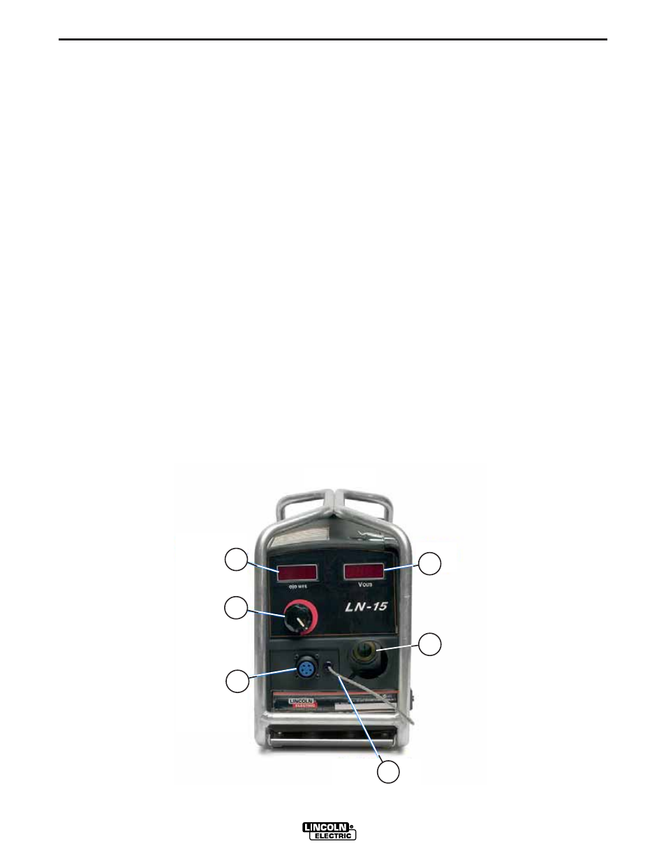
CASE FRONT CONTROLS
(See Figure B.1)
ACROSS THE ARC MODEL
1. WIRE FEED SPEED DISPLAY-The Wire Feed
Speed display shows the rate the LN-15 will feed elec-
trode during welding. The wire feed speed is calibrat-
ed to within ±2%.
2. VOLTAGE DISPLAY
-
The voltage display shows
the average arc voltage during the welding. The aver-
age voltage will continue to be shown for 5 seconds
after the end of the weld. When not welding, the dis-
play is "- - - ". The voltage is calibrated to ±2% over a
range of 10 to 45 volts.
A minus sign "-" will appear when welding with elec-
trode negative welding procedures.
3. WIRE FEED SPEED KNOB
-
The Wire Feed Speed
knob is a 3-1/2 turn potentiometer that adjusts of the
rate of feeding electrode.
4. TRIGGER CONNECTOR-5 Pin Receptacle is used
to activate the Magnum Gun Switch.
5. CONNECTOR BUSHING-This connection is for
welding conductor cable assembly.
FIGURE B.1
1
2
3
4
5
6
6. WORK CLIP LEAD-This lead must be connected
directly to the work using the spring clip.
DUAL PROCEDURE
The LN-15 supports a special "dual procedure" mode.
When activated, the wire feed speed is reduced to
83% of the set value, but no less than 50
inches/minute (1.27 m/min).
A Magnum 400 DP gun or equivalent is required to
activate the 83% dual procedure mode.