Operation, Controls and settings, M1 led 1 power switch output terminals xx on off – Lincoln Electric IM585 INVERTEC V-130-S User Manual
Page 13
B-2
OPERATION
B-2
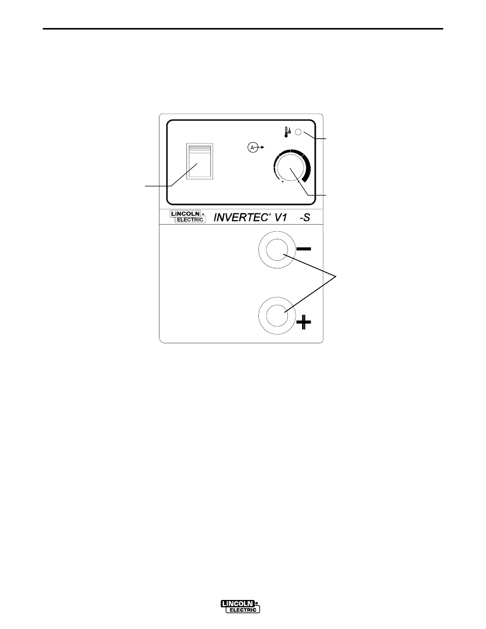
Power Switch - Controls the power input to the
machine. This rocker switch is lighted. When power is
applied to the machine the light is on.
Knob M1 - Potentiometer used to set the value of the
current required by the welding process.
LED 1 - This LED will light up when:
A) The input supply voltage is not within limits
pre-set for correct operation.
V100-S: 95VAC to 125VAC*
V130-S: 200VAC to 255VAC*
B) The machine is overheated as detected by
the internal thermostat.
* Note that input voltages that exceed 20% of nominal
may cause internal damage to the machine.
Output Terminals - These quick disconnect terminals
provide connection points for the electrode and work
cables. For positive polarity welding connect the elec-
trode cable to the positive terminal and the work cable
to the negative terminal. To weld negative polarity
reverse the electrode and work cables.
INVERTEC® V100-S & V130-S
CONTROLS AND SETTINGS
All operator controls and adjustments are located on the case front of the V100-S and V130-S machines. Refer to
Figure B.1 and the corresponding explanations.
FIGURE B.1 — CASE FRONT CONTROLS.
M1
LED 1
Power
Switch
Output
Terminals
XX
ON
OFF
XX
XX
XX
XX
XXX