Installation, Output connections, Output connection for stick welding – Lincoln Electric IM585 INVERTEC V-130-S User Manual
Page 11: Output and gas connection for tig welding, Quick disconnect plug
A-4
INSTALLATION
INVERTEC® V100-S & V130-S
A-4
OUTPUT CONNECTIONS
Refer to Figure A.1 for the location of the output terminals.
A quick-disconnect system using Twist-Mate
TM
cable plugs is
used for the welding cable connections. The electrode and
work cables included with the machine have these plugs.
An extra plug is also included with the machine if TIG weld-
ing is desired. Refer to the relevant instructions below for
more information on connecting the machine for either of
these two welding processes.
OUTPUT CONNECTION FOR STICK
WELDING
First determine the proper electrode polarity for the elec-
trode to be used. Consult the electrode data for this infor-
mation. Then connect the output cables to the output termi-
nals corresponding to this polarity. For instance, for DC(+)
welding, connect the electrode cable (which is connected to
the electrode holder) to the “+” output terminal and the work
cable (which is connected to the work clamp) to the “-” out-
put terminal. Insert the connector with the key lining up with
the keyway, and rotate approximately 1/4 turn clockwise;
until the connection is snug. Do not over tighten.
OUTPUT AND GAS CONNECTION
FOR TIG WELDING
These units do not include a TIG torch, but one may be pur-
chased separately and used with these units to do TIG
(GTAW) welding. The Lincoln LA-9 (K859-3 or K859-7 only;
no gas valve) and LA-17V (K860-11 or K860-15 only;
includes gas valve) are recommended for use with these
machines for this purpose; however, any similar TIG torch
can be used.
If the torch to be used does not have a mating Twist-Mate
plug on the end of the power cable, the power cable must
be modified to include one. The LA-9 and LA-17V fall in this
category. Cut off the lug on the end of the power cable and
attach the extra Twist Mate plug included with the machine
to the power cable per the instructions following under
QUICK DISCONNECT PLUG.
Next connect the torch cable to the appropriate output termi-
nal on the machine. Most TIG welding is done with DC(-)
polarity. For this polarity, connect the torch plug to the “-”
output terminal on the machine. Insert the connector with
the key lining up with the keyway, and rotate approximately
1/4 turn clockwise; until the connection is snug. Do not over
tighten. Connect the work cable (which is connected to the
work clamp) to the “+” output terminal in the same way.
Finally, connect the gas hose to the gas regulator on the
cylinder of gas to be used.
The machine can easily be switched between stick and TIG
welding at any time by simply swapping the stick (electrode)
and TIG (torch) cables, and reversing the connection polari-
ty if required.
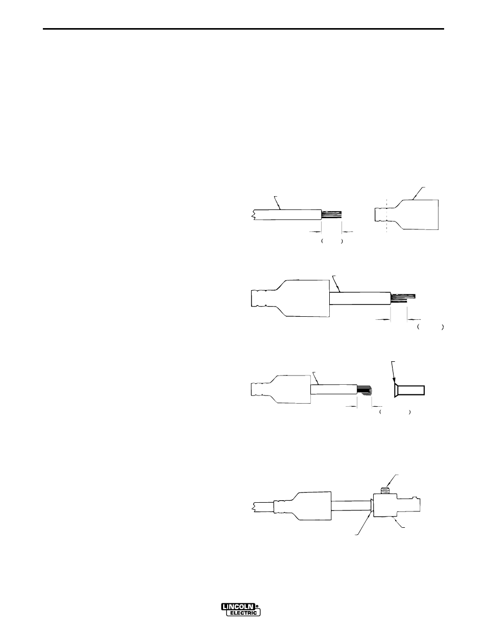
QUICK DISCONNECT PLUG
A quick disconnect system is used for the welding
cable connections. The electrode and work cables
have the plug attached, on both machines an addition-
al plug is supplied if TIG welding is to be done. The
welding plug included with the machine is designed to
accept a welding cable size of #6 to #4 (10mm
2
to
25mm
2
).
1. Cut off welding cable lug, if present.
2. Remove .75 in. (19mm) of welding cable insulation.
3. Slide rubber boot onto cable end. The boot end
may be trimmed to match the cable diameter. Use
soap or other nonpetroleum-based lubricant to
help slide the boot over the cable, if needed.
4. Cut 45-50% of the copper strands back 1/4” (6
mm).
5. Fold copper strands over cut strands and insert
into ferrule.
6. Slide the copper ferrule into the brass plug.
7. Tighten set screw to collapse copper tube. Screw
must apply pressure against welding cable. The
top of the set screw will be well below the surface
of the brass plug after tightening.
8. Slide rubber boot over brass plug. The rubber boot
must be positioned to completely cover all electri-
cal surfaces after the plug is locked into the recep-
tacle.
19 mm
.75 in.
WELDING CABLE
BOOT
TRIM, IF REQ'D
TO FIT OVER CABLE
6 mm
.25 in.
WELDING CABLE
12 mm max.
.50 in. max
WELDING CABLE
COPPER FERRULE
SET SCREW
BRASS PLUG
COPPER TUBE