Troubleshooting, Caution – Lincoln Electric IM420 IDEALARC DC-1000 User Manual
Page 20
E-4
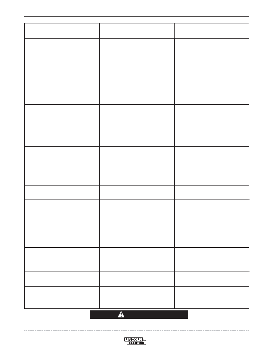
TROUBLESHOOTING
E-4
IDEALARC® DC-1000
Observe all Safety Guidelines detailed throughout this manual
If for any reason you do not understand the test procedures or are unable to perform the tests/repairs safely, contact your
Local Lincoln Authorized Field Service Facility for technical troubleshooting assistance before you proceed.
CAUTION
PROBLEMS
(SYMPTOMS)
POSSIBLE
CAUSE
RECOMMENDED
COURSE OF ACTION
Output control not functioning on remote
control.
Poor starting on CV(S) Sub-Arc.
Poor bead shape or erratic arc on CV(S)
Sub-Arc.
Poor starting on CV(I) Innershield and
CV(S) Sub-Arc.
Poor arc characteristics on CV(I)
Innershield or other open arc processes.
Poor arc characteristics on all process-
es.
Poor performance (including arc out-
ages) while welding at low current (less
than 450 amps) when connected to 1000
amp “+” output studs.
Machine frequently shuts off while using
the 500 amp “+” output stud.
1. Output control switch in wrong posi-
tion.
2. Faulty output control switch.
3. Faulty remote control potentiometer.
4. Leads or connections open in control
circuit.
5. Faulty firing or control circuit P.C.
board.
1. Improper procedures or setting of
controls.
2. Poor electrode or work connection.
3 3CR reed switch inoperative.
4 Faulty control board.
1. Improper procedures.
2. Defective 3CR reed switch.
3. Faulty control board.
4. Defective main SCR bridge.
1. Defective 3CR reed switch.
2. Faulty control board.
1. Mode switch in CV(S) Sub-Arc mode.
2. Defective main SCR bridge.
1. Defective control board.
2. Defective firing board.
3. Defective main SCR bridge.
1. Insufficient output inductance.
1. Effective current demand well over
500 amperes.
1. Place switch in “Output Control
Remote”.
2. Check and replace if found faulty.
3. Check and replace if found faulty.
(Voltage from 75 to 77 should be 3 to
5V).
4. Check all leads and connections,
internal or remote, for continuity;
repair if necessary.
5. All light emitting diodes must be lit on
both P.C. boards, except LED4 on
control/fault board. See P.C. board
troubleshooting guide.
1. See instruction manual and proce-
dures.
2. Repair connections.
3. Check reed switch voltage leads 216
to 220. Idle voltage is about 8V; when
welding, voltage must go to zero.
4. Replace. See P.C. board trou-
bleshooting guide.
1. See instruction manual and proce-
dures.
2. Check reed switch per item c. of pre-
vious Table above.
3. Replace. See P.C. board trou-
bleshooting guide.
4. Check and replace if defective.
1. Replace.
2. Replace.
1. Place mode switch in CV(I)
Innershield mode.
2. Check and replace if defective.
1. Check and replace if defective. See
P.C. board troubleshooting guide.
2. Check and replace if defective. See
P.C. board troubleshooting guide.
3. Check and replace if defective.
1. Use the 500 amp “+” output stud.
1. Use the 1000 amp “+” output studs.