Troubleshooting, Caution – Lincoln Electric IM420 IDEALARC DC-1000 User Manual
Page 19
E-3
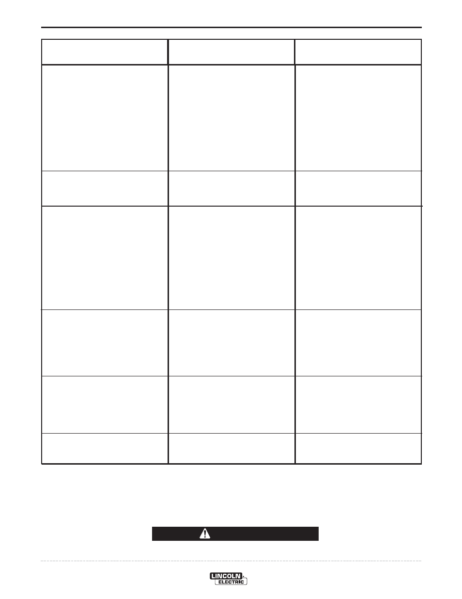
TROUBLESHOOTING
E-3
IDEALARC® DC-1000
Observe all Safety Guidelines detailed throughout this manual
If for any reason you do not understand the test procedures or are unable to perform the tests/repairs safely, contact your
Local Lincoln Authorized Field Service Facility for technical troubleshooting assistance before you proceed.
CAUTION
PROBLEMS
(SYMPTOMS)
POSSIBLE
CAUSE
RECOMMENDED
COURSE OF ACTION
Machine has maximum output but
not control.
Machine has minimum output and no
control.
Machine does not have maximum
output.
Variable or sluggish welding arc.
Machine has output but trips off
immediately when wire feed unit
start button is pressed.
Machine will not shut off.
Output control not functioning on the
machine
(1)
.
1. Output control switch (SW3) in wrong
position.
2. Output control switch faulty.
3. Open in feedback circuitry.
4. Faulty control or firing circuit P.C.
boards.
5. Output control potentiometer circuit
open (Lead 75).
1. Terminals 73, 74, 75, 76 or 77
grounded to
positive
output.
1. One input fuse blown.
2. One phase of main transformer open.
3. Faulty control or firing circuit P.C.
boards.
4. Output control potentiometer defec-
tive.
5. Output control potentiometer leads
open - 76, 77, 226, 236, 237, 238.
1. Machine has either an internal or
external short circuit on the output.
2. Faulty control P.C. board.
3. Terminals 73, 74, 75, 76, 77 ground-
ed to negative output terminal.
1. Poor work or electrode connection.
2. Welding leads too small.
3. Welding current or voltage too low.
4. Defective main SCR bridge.
1. Input contactor contacts frozen.
2. Faulty 2CR relay.
1. Check position of switch.
2. Check switch and replace if faulty.
3. Check wiring and control and firing
circuit P.C. board wiring harness
plugs.
4. All light emitting diodes must be lit,
except LED4 on the control/fault
board. See P.C. board troubleshoot-
ing guide.
5. Check and replace potentiometer if
faulty. Check wiring of Lead #75.
1. Check 73, 74, 75, 76 or 77 for ground
to positive output circuit.
1. Check and replace if blown after
checking for reason for blown fuse.
2. Check for open and repair.
3. All light emitting diodes must be lit on
both P.C. boards, except LED4 on
control/fault board. See P.C. board
troubleshooting guide.
4. Check and replace if faulty.
5. Repair.
1. Check internally and externally for
any shorts and remove or repair.
2. Replace control board. See P.C.
board troubleshooting guide.
3. Check for grounded 73, 74, 75, 76,
77.
1. Check and clean all connections.
2. Check table in instruction manual.
3. Check procedures for recommended
settings.
4. Check and replace if defective.
1. Check and replace if necessary.
2. Check and replace if necessary.
(1)
If connected to an LN-9 or NA-5, disconnect leads 73, 74, 75 before troubleshooting.