Troubleshooting, Caution – Lincoln Electric IM420 IDEALARC DC-1000 User Manual
Page 18
E-2
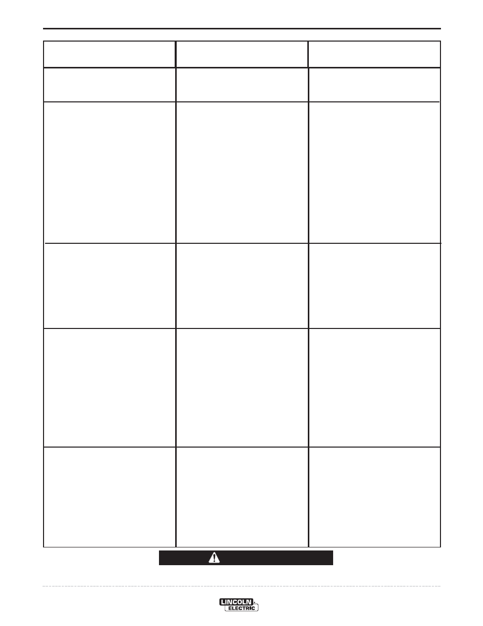
TROUBLESHOOTING
E-2
IDEALARC® DC-1000
Observe all Safety Guidelines detailed throughout this manual
If for any reason you do not understand the test procedures or are unable to perform the tests/repairs safely, contact your
Local Lincoln Authorized Field Service Facility for technical troubleshooting assistance before you proceed.
CAUTION
PROBLEMS
(SYMPTOMS)
POSSIBLE
CAUSE
RECOMMENDED
COURSE OF ACTION
I
nput contactor (1CR) chatters.
Machine input contactor does not oper-
ate.
Input contactor pulls in when start button
is pressed, but immediately drops out.
Machine input contactor operates but no
output when trying to weld.
1. Faulty input contactor (1CR).
2. Low line voltage.
3. Faulty 2CR relay.
1. Supply line fuse blown.
2. Contactor power circuit dead.
3. Broken power lead.
4. Wrong input voltage.
5. Secondary or choke thermostat open.
6. Open input contactor coil.
7. Faulty stop/start push button switch.
8. Faulty 2CR relay.
9. Defective control board.
1. Defective start/stop push button.
2. Defective 1CR interlock.
3. Ground fault between control termi-
nals 73, 74, 75, 76 or 77 and nega-
tive output terminal.
4. Short on output terminals with 2-4
jumpered.
5. Defective control board.
1. Electrode or work lead loose or bro-
ken.
2. Open main transformer (T1) primary
or secondary circuit.
3. Output pilot relay 4CR not operating
or faulty.
4. Firing circuit P.C. board not connect-
ed or is faulty.
5. If using 500 amp stud, choke circuit
may be open.
1. Repair or replace.
2. Check input power.
3. Repair relay.
1. Replace if blown - look for reason
first.
2. Check pilot transformer T2 and asso-
ciated leads.
3. Check input voltage at contactor.
4. Check voltage against instructions.
5. Check for overheating; make sure fan
is operating and there is no obstruc-
tion to free air flow. Replace faulty
thermostat.
6. Replace coil.
7. Replace switch.
8. Replace relay.
9. Replace control board. See P.C.
board troubleshooting guide.
1. Check and replace if necessary.
2. Repair or replace.
3. Check 73, 74, 75, 76 or 77 for ground
to negative output circuit.
4. Remove short.
5. Replace control board. See P.C.
board troubleshooting guide.
1. Repair connection.
2. Repair.
3. Check relay pull-in by connecting a
jumper across terminals 2 and 4 on
DC-1000 terminal strip. Replace if
faulty.
4. All nine light emitting diodes (LED1
thru LED9) must be lit. See P.C.
board troubleshooting guide.
5. Repair.