Installation, A-6 auxiliary power and control connections – Lincoln Electric IM669 RED-D-ARC DC-600 User Manual
Page 14
A-6
INSTALLATION
A-6
AUXILIARY POWER AND
CONTROL CONNECTIONS
Located at the left side of the front of the welder
behind a hinged cover is a 115VAC GFCI receptacle
for auxiliary power. On the right side of the case front
is a 14 Pin MS type receptacle for connection of auxil-
iary equipment such as wire feeders. Also, terminal
strips with 115VAC and connections for auxiliary
equipment are located behind the hinged access
panel on the right side of the case front. (see Auxiliary
Power Table for details)
115VAC GFCI RECEPTACLE (60 HERTZ MODELS
ONLY)
The 115VAC GFCI receptacle is protected by a circuit
breaker located on the nameplate. The receptacle is a
NEMA 5-15R.
AUXILIARY POWER TABLE
Voltage and Circuit Breaker Ratings at Auxiliary Power
Connections for Various Models
Auxiliary
60 Hz
Power
Models
Connections
At GFCI
115V 15A
Receptacle
Terminal strip
115V 15A
terminals 31 & 32
MS-Receptacle
115V 15A
pins A & J
MS-Receptacle
42V 10A
pins I & K
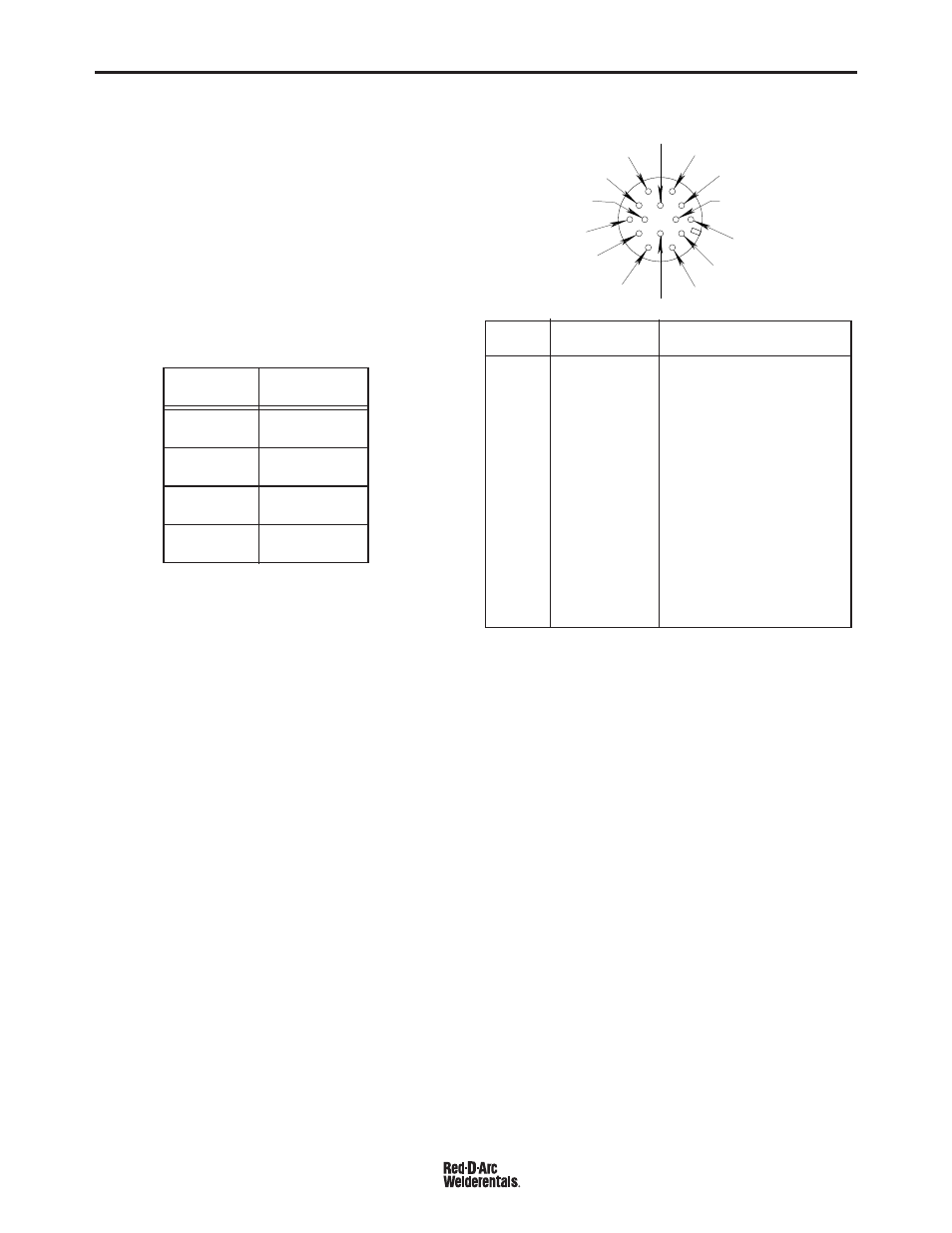
FIGURE A.6 FRONT VIEW OF 14-PIN
CONNECTOR RECEPTACLE
PIN
LEAD NO.
FUNCTION
A
32
115 VAC
B
GND
Chassis Connection
C
2
Trigger Circuit
D
4
Trigger Circuit
E
77
Output Control
F
76
Output Control
G
75
Output Control
H
21
Work Sense Connection
2
I
41
42 VAC
J
31
115 VAC
1.
K
42
42 VAC
L
---
---
M
---
---
N
---
---
F = 7 6
G = 7 5
H = 2 1
I = 4 1
J = 3 1
K = 4 2
A = 3 2
B = G N D
C = 2
D = 4
E = 7 7
L
N
M
1.
115VAC circuit is on all models.
2.
As shipped from the factory Lead #21 from the 14 Pin connector is
connected to “-21” on the terminal strip (T.S.2). This is the config-
uration for positive welding. If welding negative polarity, connect
lead #21 to the “+21” connection point on the terminal strip
(T.S.2).
14 PIN MS TYPE RECEPTACLE
(For MS3106A-20-27PX Plug. L.E.C. Part #S12020-32)
Refer to the figure A.6 for the available circuits in the
14 pin receptacle.
42 VAC is available at receptacle pins I and K.
A 10 amp circuit breaker protects this circuit.
115 VAC is available at receptacle pins A and J (All
Models). A 15 amp circuit breaker protects this circuit.
Note that the 42 VAC and 115 VAC circuits are electri-
cally isolated from each other.
DC-600 RED-D-ARC