Accessories, Ln-7 idealarc dc-600 – Lincoln Electric IM306 IDEALARC DC-600 User Manual
Page 31
C-7
ACCESSORIES
C-7
IDEALARC DC-600
LN-7 IDEALARC DC-600
1.
Disconnect main AC input power to the
IDEALARC DC-600.
2.
Set the IDEALARC DC-600 ON/OFF PUSH
BUTTON to OFF.
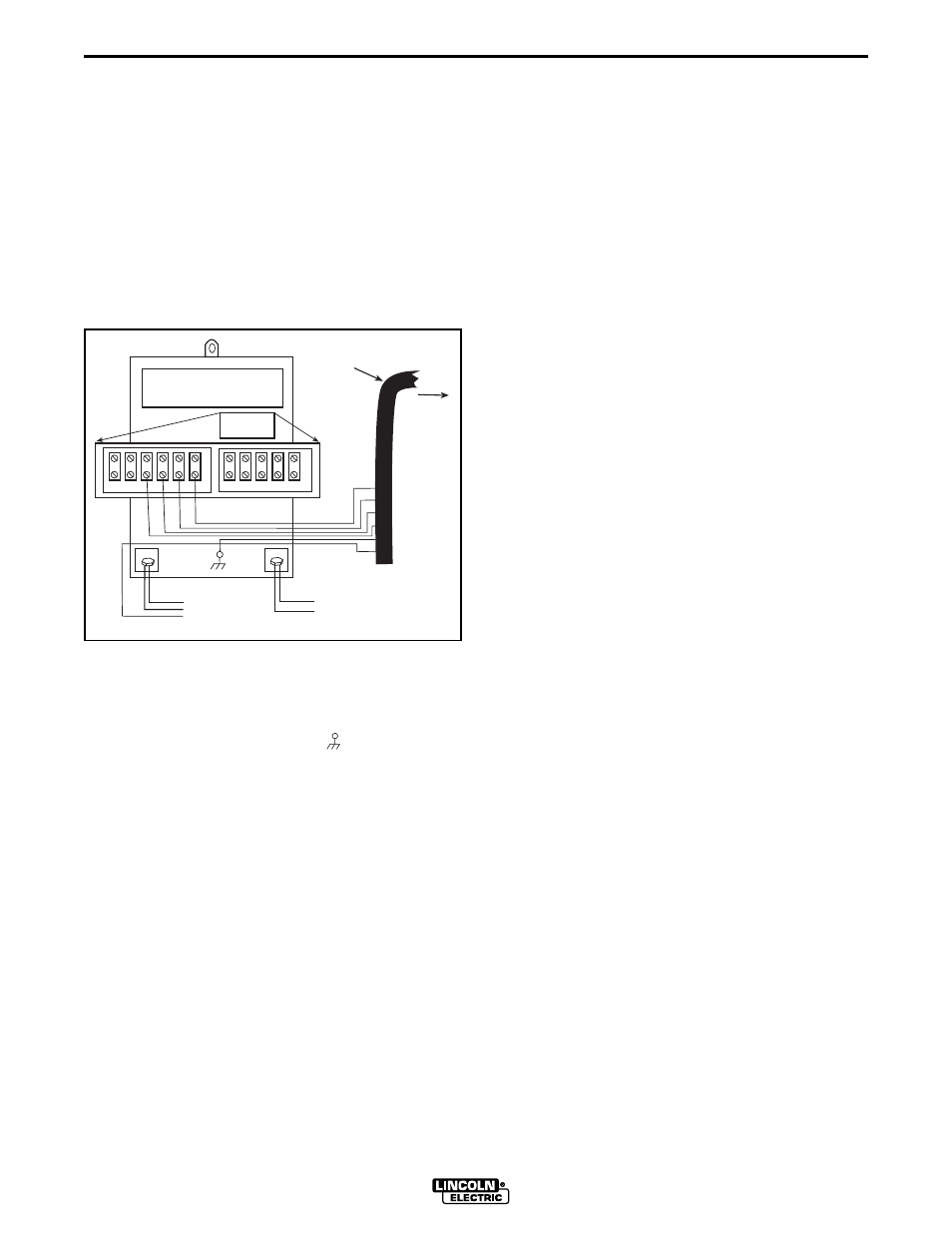
3.
Connect the wire feeder control cable leads to the
IDEALARC DC-600 terminal strip as shown in
Figure C.8.
FIGURE C.8 - LN-7 WIRE FEEDER CONNEC-
TION TO THE IDEALARC DC-600
4.
Connect the wire feeder control cable ground lead
to the frame terminal marked ( ).
NOTE: The IDEALARC DC-600 must be properly
grounded.
5.
PERFORM THIS STEP ONLY IF THE LN-7 IS
EQUIPPED WITH A METER KIT.
Extend wire feeder control cable lead #21 so it
can be connected directly to the work piece.
a.
Make a bolted connection using AWG #14 or
larger insulated wire. Tape the bolted con-
nection with insulating tape.
NOTE: If the work cable length is less than 25
feet and the connections to the work piece are
secure, then wire feeder control cable lead #21
can be connected directly to the DC-600 terminal
strip.
b.
An S-16586- X remote voltage sensing work
lead is available for this purpose.
c.
Keep the #21 lead electrically separate from
the work cable circuit and connection.
d.
Tape the #21 lead to work cable for ease of
use.
NOTE: The connection diagram shown in Figure C.8
shows the electrode connected for positive polarity.
To change polarity:
a.
Set the IDEALARC DC-600 ON/OFF PUSH
BUTTON to OFF.
b.
Move the electrode cable to the Negative (-)
output terminal.
c.
Move the work cable to the Positive (+) output
terminal.
d.
Set the IDEALARC DC-600 CONTROL
CIRCUIT POLARITY SWITCH to NEGATIVE.
21 4
2 31 32
75 76 77 80 81
–
+
NEGATIVE
TO WORK
ELECTRODE
CABLE TO LN
CONDUCTOR
BLOCK
LN -7 WIRE
FEEDER
CONTROL
CABLE
77
76
75
32
31
2
4
POSITIVE
TO LN-7
INPUT
CABLE
PLUG
21
GND