Accessories, Connecting the na-5 to the idealarc dc-600 – Lincoln Electric IM306 IDEALARC DC-600 User Manual
Page 29
C-5
ACCESSORIES
C-5
IDEALARC DC-600
CONNECTING THE NA-5 TO THE
IDEALARC DC-600
NOTE: For optimum performance use the NA-5 with
IDEALARC DC-600 codes 8288 and above.
1.
Disconnect main AC input power to the IDE-
ALARC DC-600.
2.
Set the IDEALARC DC-600 ON/OFF PUSH
BUTTON to OFF.
3.
Connect the wire feeder control cable leads to the
IDEALARC DC-600 terminal strip as shown in
Figure C.6.
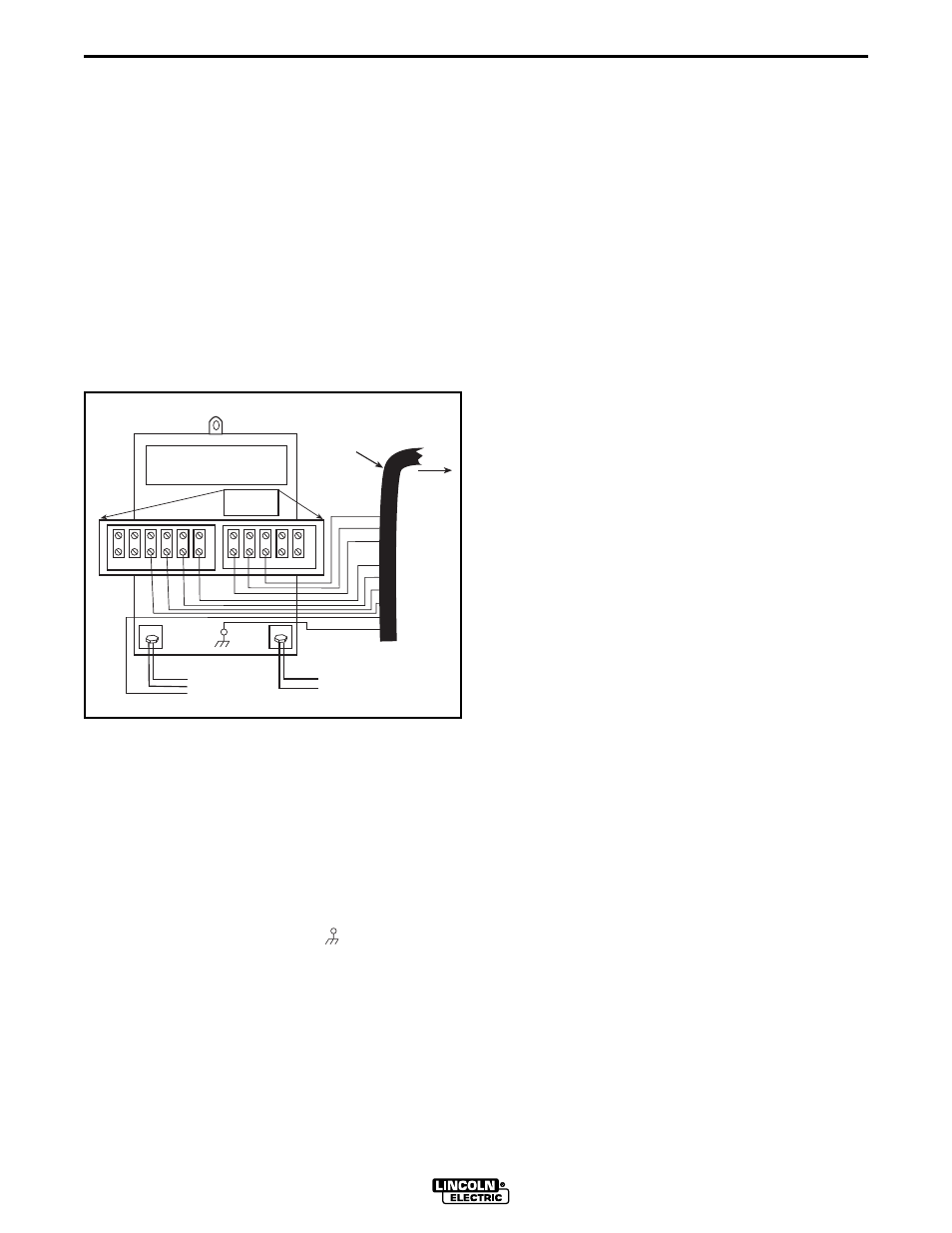
FIGURE C.6 - NA-5 WIRE FEEDER CONNEC-
TION TO THE IDEALARC DC-600
NOTE: If using a K215 control cable, connect
control cable leads #75, #76, and #77 to the
matching #75, #76, and #77 terminals on the ter-
minal strip of the IDEALARC DC- 600.
4.
Connect the wire feeder control cable ground lead
to the frame terminal marked ( ).
NOTE: The IDEALARC DC-600 must be properly
grounded.
5.
Extend wire feeder control cable lead # 21 so it
can be connected directly to the work piece.
a.
Make a bolted connection using AWG #14 or
larger insulated wire. Tape the bolted con-
nection with insulating tape.
b.
An S-16586- X remote voltage sensing work
lead is available for this purpose.
c.
Keep the # 21 lead electrically separate from
the work cable circuit and connection.
d.
Tape the # 21 lead to work cable for ease of
use.
6.
Connect NA-5 wire feeder control jumpers on
Voltage Control Board. See NA-5 Operator's
Manual.
a.
Connect red jumper on Voltage Control Board
to pin "S."
b.
Connect white jumper on Voltage Control
Board to pin "B."
NOTE: The connection diagram shown in Figure C.6
shows the electrode connected for positive polarity.
To change polarity:
a.
Set the IDEALARC DC-600 ON/OFF PUSH
BUTTON to OFF.
b.
Move the electrode cable to the Negative (-)
output terminal.
c.
Move the work cable to the Positive (+) output
terminal.
d.
Set the IDEALARC DC-600 CONTROL
CIRCUIT POLARITY SWITCH to NEGATIVE.
NOTE: For proper NA-5 operation, the electrode
cables must be secured under the clamp bar on the
left side of the NA-5 Control Box.
21 4
2 31 32
75 76 77 80 81
–
+
NEGATIVE
TO WORK
ELECTRODE
CABLE TO WIRE
FEEDER
LN8 OR LN 9
WIRE
FEEDER
CONTROL
CABLE
C
B
A
32
31
2
4
POSITIVE
TO INPUT
CABLE
21
GND