Accessories – Lincoln Electric IM306 IDEALARC DC-600 User Manual
Page 26
C-2
ACCESSORIES
C-2
IDEALARC DC-600
5.
Attach the MULTI-PROCESS SWITCH bracket
across the front of the machine with the flange
down. Use the long, self-tapping screws and lock
washers provided. The bracket should be on the
outside of the side panel. See Figure C.3.
NOTE: If the machine does not have any holes in
the front of the machine, use the switch template
and drill two .153" diameter holes.
6.
Position the MULTI-PROCESS SWITCH at the
front of the machine. See Figure C.3.
FIGURE C.3 - ATTACHING THE MULTI-
PROCESS SWITCH BRACKET.
7.
Route the MULTI-PROCESS SWITCH control
leads through the strain-relief box connectors and
into the terminal strip. The wire feeder control
cable is routed through the strain-relief box con-
nector also. See Figure C.3.
8.
Connect the control leads from the MULTI-
PROCESS SWITCH to terminals #2 and #4 on
the IDEALARC DC-600's terminal strip.
9.
Position the MULTI-PROCESS SWITCH flush
with the front of the machine about 2" lower than
the bracket. Slide the switch straight up to the
bracket.
10. Check that the bottom of the switch is hooked
behind the top of the bottom louver.
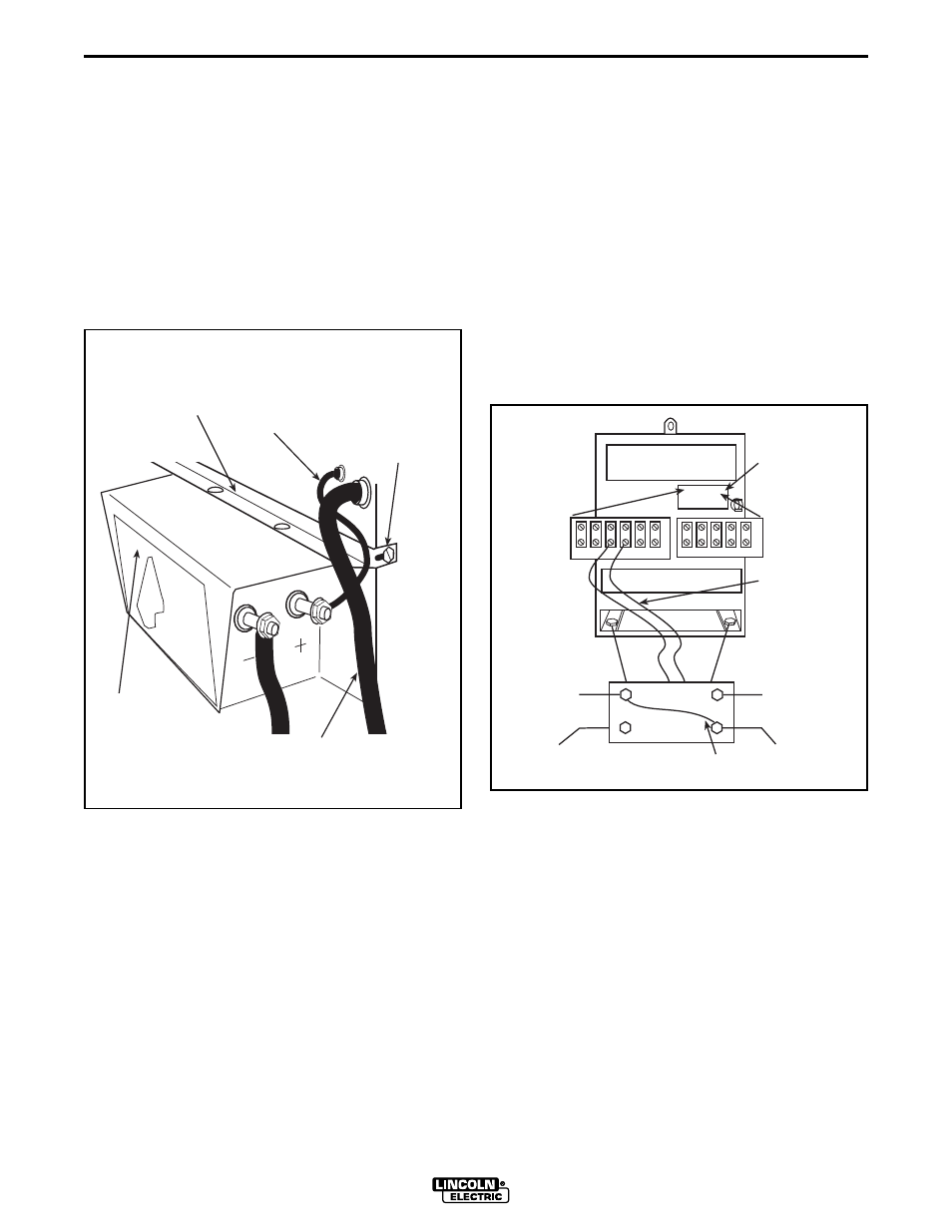
11. Connect the right cable from the MULTI-
PROCESS SWITCH (facing the front of the
machine) to the IDEALARC DC-600 positive (+)
output terminal. See Figure C.4.
FIGURE C.4 - MULTI-PROCESS SWITCH
CABLE CONNECTIONS.
12. Connect the left cable from the MULTI-PROCESS
SWITCH (facing the front of the machine) to the
IDEALARC DC-600 negative (-) output terminal.
See Figure C.4.
MULTI-
PROCESS
SWITCH
BRACKET
WIRE FEED
CONTROL
CABLE
MULTI-
PROCESS
SWITCH
CONTROL
LEADS
SELF TAPPING
SCREWS
(DRILL .153"
HOLE IF
NEEDED)
WORK
CABLE
WORK
ELECTRODES
21 4
2 31 32
75 76 77 80 81
TERMINAL
STRIP
POSITIVE (+)
OUTPUT
STUD
–
+
NEGATIVE (–)
OUTPUT
STUD
ELECTRODE
CABLE
WORK
CABLE
ELECTRODE
CABLE
JUMPER (IF NEEDED
SEE INSTRUCTIONS)
+
CONTROL
LEADS
STICK AIR/CARBON
ARC WELDING
EQUIPMENT
WIRE
FEEDER