Information panel – Brocade FCoE Switch Module for IBM BladeCenter Installation and User’s Guide User Manual
Page 37
© Copyright IBM Corp. 2010
23
Chapter 5. Information panels, LEDs, and external ports
This chapter describes the information panels and LEDs on the switch module and identifies the
external ports on the information panels.
NOTE
The illustrations in this document might differ slightly from your hardware
Information panel
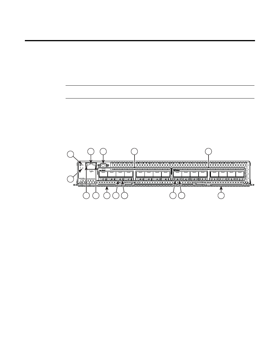
The front panel of the switch module contains information LEDs, eight FC and eight CEE SFP+
module port connectors, one mini-USB console port connector, and one Ethernet port connector,
as shown in the following illustration.
FIGURE 12
high speed switch module front panel
The switch module information panel contains the following components:
•
LEDs that display the following information:
-
The status of the switch module and its network connection
-
The status of the external connections to the switch module
For further details about LEDs, see “Information LEDs” on page 24.
•
Eight FC SFP+ port connectors to attach SFP+ modules. They are numbered 23-30 right to left.
•
Eight FCoE/CEE SFP+ port connectors to attach SFP+ modules. They are numbered 15-22
right to left
1
Status/Fault LED (amber)
8
CEE port link status LED (green)
2
Power LED (green)
9
FC port fault status LED (amber)
3
Ethernet port (RJ45)
10
FC port Tx/Rx link status LED (green)
4
Console port (mini-USB)
11
Ethernet port speed LED (green)
5
Fibre Channel ports (23-30 - right to left)
12
Ethernet port Link LED (green)
6
CEE ports (15-22 - right to left)
13
Release levers(2)
7
CEE port fault status LED (amber)
4
3
3
5
6
12
11
13
13
10 10
9
8
10
7
2
1