Step 3 - install the cross pan, Step 4 - install control box and keypad, Step 5 - install cable tray – Anthro Elevate II Adjusta Assembly Instructions User Manual
Page 5
Elevate II Adjusta Assembly Instructions
5
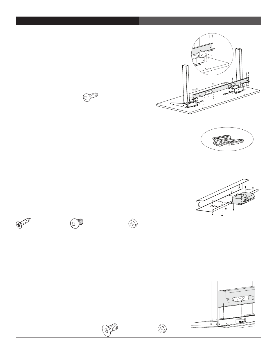
STEP 3 - INSTALL THE CROSS PAN
Align the Cross Pan with the Leg Assemblies so the pair of flanges
on the pan line up with the pre-drilled holes on the table. Attach
the back of the pan to the top with four 1" MDF Screws
(325-5580-00) and attach the front of the pan to the top with
three 1" MDF Screws.
Attach the pan to each leg housing with two M6x14 flat-head
fasteners using the Anthro driver.
Tighten all fasteners.
STEP 4 - INSTALL CONTROL BOX AND KEYPAD
Align the keypad and its slider housing with the four pre-drilled holes at the
front of the keyboard surface so the buttons are face-down at the front edge
of the keyboard surface and the flat side of the housing is against the shelf.
The keypad can also be installed directly to the worksurface without the slider
housing, either so it extends in front of the table or so it's set back a bit.
Using four Phillips Head Screws (325-5370-00), attach the keypad and its
housing (if desired) to the front of the worksurface. Install these screws by
hand. Too much torque can damage the plastic.
Align the Control Box with the Cable Tray so the ports face up and the holes
on the Control Box line up with the holes on the Cable Tray. The Control Box
installs at the center of the tray on the 48w table. The 60w table comes with
three installation points (left, center, and right) to allow space for a power bar
or surge protector in the tray. Attach the box to the tray with four 1/2" Button-
head Screws and four Nylock Nuts using your own 3/8" socket (or the 3-way
wrench provided) and the smallest hex key (1/8") in your kit.
1/2”Button-hd Screw
325-5193-00
Nylock Nuts
325-5186-00
3/4” Phillips Screw
325-5370-00
Keypad and Housing
Attaching the Control Box to the Cable Tray
of a shallow 48" wide table.
STEP 5 - INSTALL CABLE TRAY
Align the Cable Tray with the back of the table so the holes on the threaded posts on the cross pan line up with the holes
on the cable tray. Attach the tray to the pan with three Nylock Nuts using your own 3/8" socket or the 3-way wrench
provided. (The plastic end of the nut faces up.)
Connect a 1-meter Control Box Cable to each leg cable, then plug each into a port on the Control Box through the
opening in the support pan. Feed extra cable length through an opening in the support pan so it's organized in the Cable
Tray.
Route the Keypad's cable back to the Cross Pan and plug it into the Control Box.
Feed extra cable length through an opening in the support pan so it's organized
in the Cable Tray.
Plug the Power Cord into the Control Box.
Use the provided cable clips to route and organize cords. Install one cable clip
next to the Leg Gusset for the Keypad Cord. Install the other clip next to the
Cross Pan for the Control Box Cables.
1” Button Hd PB Screw
325-5580-00
1/2” Flat-head Screw
325-5193-00
Nylock Nuts
325-5186-00