Figure 8 - roof curb specifi cations – Sterling RT User Manual
Page 9
9
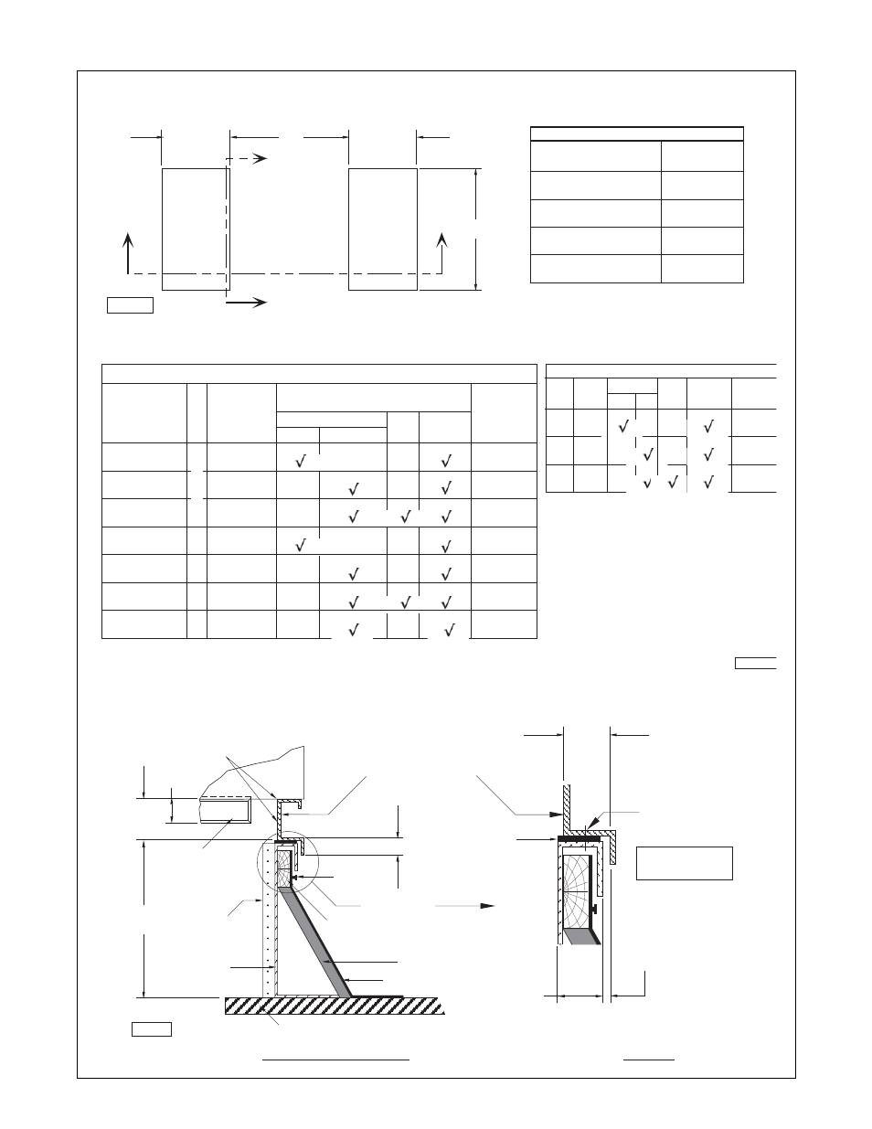
Figure 8 - Roof Curb Specifi cations
20-7/8"
(530)
20-7/8"
(530)
A
*
Return
Air
Opening
Supply
Air
Opening
E
*
Section
Y-Y
Section
X-X
Capacity
[ CA ]
Dimension
E *
10/15
20/25/50
30/35/60/70
40/80/12
26"
(660)
37"
(940)
48"
(1219)
53-1/2"
(1359)
Unit Type [ U T ] “RT, PV or AH”
* All Dimensions Shown Have Been Calculated To
Include A One (1) Inch Clearance Around Return
And Supply Ducts.
D3809-4
**
Rooftop
Arrangement
[ RA ]
C, E
J
L
C, E
J
L
J
Blower
High CFM
St'd.
Supply
Plenum
*
Dimension
A
Coil
50-7/8"
(1292)
87-1/16"
(2211)
113"
(2871)
76-7/8"
(1952)
139"
(3531)
113"
(2871)
139"
(3531)
Unit Specifications
( References )
Capacity
[ CA ]
10 - 40
20 - 40
10 - 40
50 - 80
50 - 80
50 - 80
12
**
Rooftop Arrangements [ RA ] B, D, G, K, M, P, S & U Are Without a
Return Air Dimensions For These Units Rooftop Openings. Refer To Unit Submittals For More Detail.
Unit Type [ U T ] “RT or PV”
**
[ RA ]
N, R
T
W
[ CA ]
*
A
24-7/8"
(631)
Unit Type [ UT ] “AH”
St'd.
Hi
Blower
Coil
Supply
61-1/16"
(1551)
87-1/16"
(2211)
20
or 40
20
or 40
20
or 40
TRI
SINGLE
DU
AL
FURNA
CE
D3809-1
2" (50)
3/8" (10) Clearance
Should Be Maintained
On Each Side To Insure
Proper Installation.
1-7/8" (22)
Anchor
Location
*
Field Supplied
By Others
D3809-2
4"
(102)
12"
(305)
Nailer
(Wood Strip)
Nail
*
Felt
*
Cant
*
1" (25)
Gasketing
Roof
Unit
Seal All Corners,
Seams & Gaps.
Unit Base
Side Rail Flange
With Curb Cap
Optional
Insulation
See Detail K
Detail K
Curb Rail
Ass'y.
Section Curb Side Rail
2-1/2"
(64)
Damper