Sterling RT User Manual
Page 12
12
Outdoor line voltage conduits leading into
the unit should be installed to prevent rain
from wetting any high voltage wire. Locate
the thermostat in accordance with the
instructions supplied with the thermostat.
All field wiring must have a minimum
temperature rating of 185°F (85°C). Control
wiring must be a minimum of 18 gauge wire
size. Control wiring must be sized for the
length of run.
Locate line voltage disconnect box per local
codes. If mounting the disconnect box to the
unit, never mount it to an unit access panel.
Possible locations include the front of the
blower or fi lter section, the outdoor air hood or
the rear of the supply plenum (See Figure 11).
Electrical conduit must be routed so as not to
interfere with removal of any access panel.
NOTICE: Should any original wire
supplied with the unit have to be
replaced, it must be replaced with wiring
having a temperature rating of at least
221°F (105°C).
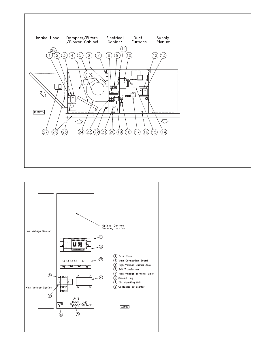
Figure 9 - Standard Blower Cabinet, Single Duct Furnace with Supply Plenum & Various Options Shown
1. Mixed Air Controller
2. Return Firestat
3. Economizer
4. Filters
5. Blower Motor
6. Reverse Air Flow Switch
7. Clogged Filter Switch
8. High voltage Barrier and Lamp
and Circuit Breaker Mount
9. Main Connection Board
with Fan Time Delay and Func-
tion Relays
10. Power
Ventor
Relay
11. Freezestat
12. Supply
Firestat
13. Duct
Thermostat
14. Primary Safety Limit
15. Power
Ventor
Motor
16. Gas Piping Inlet
17. Gas
Valve
18. High Limit Safety Switch
19. Transformer
20. Electrical
Wiring
Inlet
21. High
Voltage
Terminal
Block
22. Door Safety Switch
23. Contactor
24. Centrifugal Blower Assembly
25. Damper
Motor
26. Outside and Return Dampers
27. Enthalpy
Controller
Economizer
28. Ambient
Lockout
Figure 10 - Electrical Cabinet
[Power Vent “PV” unit shown]