Sterling RT User Manual
Page 19
19
4. Remove the locking screws holding the burnerdrawer
assembly in position.
5. Slide the burner drawer out of the duct furnace.
6. Removal of burners is accomplished by sliding burner
towards manifold, compressing locating spring, until
the rear of the burner clears slot in back of burner
drawer.
7. With burner drawer removed from duct furnace,
inspect the inside surfaces of the heat exchanger.
Wire brush if necessary.
8. Remove any dirt, dust or other foreign matter from
the burners using a wire brush and/or compressed
air. Insure all parts of the burner are unobstructed.
Inspect and clean pilot burner if necessary.
9. Reassemble the duct furnace by replacing all parts
in order.
10. Light unit per the unit lighting instructions.
11. Check the burner adjustment. See the “Primary Air
Adjustment” section of this manual.
12. Check all gas control valves and pipe connections for
leaks.
Under no circumstance should
combustible material be located within the speci-
fi ed clearances. Failure to provide proper clear-
ance could result in personal injury or property
damage from fi re.
13. Check the operation of the duct furnace gas valve by
lowering the setting of the thermostat, stopping the
operation of the duct furnace. The duct furnace gas
valve should close, extinguishing the pilot and main
burner fl ames.
14. Inspect and service the blower section of the system.
The unit should be thoroughly checked before the start
and at the end of each heating and cooling season.
1. Motors and belts should be inspected.
2. Tighten belts if loose.
3. Check and clean DX or Chilled Water coil twice yearly,
if unit is so equipped per manufacturer’s service
manual. Chilled Water coil must be winterized at
beginning of heating season (i.e. drain water from
coil per manufacturer’s instructions).
4. Check air throughput at beginning of heating season
to confirm unit operation is within the specified
temperature rise range.
5. At beginning of heating season clear Condensate
Drain Pan and P-trap of water if unit is equipped with
DX or Chilled water coil. Clean out drain pan and fi ll
P-trap with a non-toxic glycol solution.
6. Evaporative cooler must be cleaned and maintained
per manufacturer’s instruction frequently during the
operating season.
7. Inspect Control Dampers during periodic maintenance.
Damper pivot points should be cleaned to ensure free
damper operation.
8. Blower wheels should be checked periodically for dirt
build-up on blades. Clean as required.
FILTERS
It is recommended that air fi lters be changed or cleaned
at least four times a year. More frequent attention to fi lters
is required if the air being handled by the unit is unusually
dirty. Air fl ow reduction, caused by the dirty air fi lters, will
increase the discharge air temperature and may cause
unit cycling on the primary limit.
Filters (by others) should be serviced regularly and
changed or washed when necessary to maintain the
required air throughput. In a dusty environment, fi lters
may clog up in less than one month.
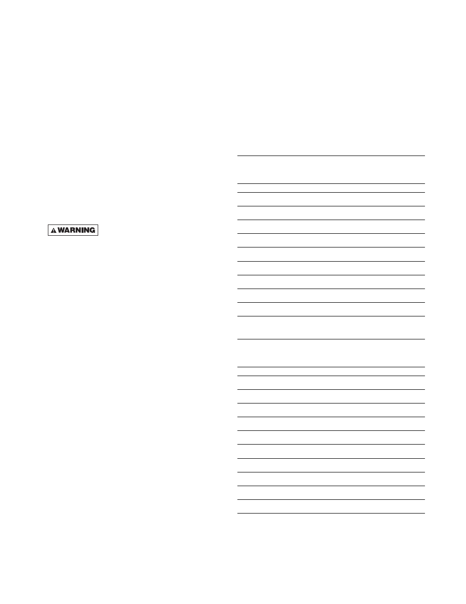
High CFM Blower Air Filter Size Requirements
Number of Filters Required
Unit Input
16 x 20 (in)
20 x 20 (in)
200 MBtuh (58.6 kW)
8
250 MBtuh (73.2 kW)
8
300 MBtuh (87.9 kW)
8
4
350 MBtuh (102.6 kW)
8
4
400 MBtuh (117.2 kW)
12
500 MBtuh (146.5 kW)
8
600 MBtuh (175.8 kW)
8
4
700 MBtuh (205.1 kW)
8
4
800 MBtuh (234.4 kW)
12
1,200 MBtuh (351.6kW)
12
Standard CFM Blower Air Filter Size Requirements
Number of Filters Required
Unit Input
16 x 20 (in)
20 x 20 (in)
100 MBtuh (29.3 kW)
4
150 MBtuh (44.0 kW)
4
200 MBtuh (58.6 kW)
4
250 MBtuh (73.2 kW)
4
300 MBtuh (87.9 kW)
4
2
350 MBtuh (102.6 kW)
4
2
400 MBtuh (117.2 kW)
6
500 MBtuh (146.5 kW)
4
600 MBtuh (175.8 kW)
4
2
700 MBtuh (205.1 kW)
4
2
800 MBtuh (234.4 kW)
6