Installation, 1 mechanical considerations, 2 fast loop line size and response times – Yokogawa Advanced Reflux Sampler User Manual
Page 9
9
All Rights Reserved. Copyright © 2011, Yokogawa Electric Corporation. Subject to change without notice.
April 2011
IM 11A00V01-01E-A
5.1 Mechanical Considerations
Typically, the YARS will be subject to large vibration conditions and therefore a sound mechanical installation is required.
While flange mounting to the customer supplied process isolation valve provides an installation, it is also recommended
that the upper section of the YARS be secured mechanically. The heat exchanger and controller give the YARS ‘top-heavy’
properties that should be considered during installation.
It is also desirable to have ready access to the unit such that routine maintenance checks can be made on the operation
of the unit in a safe manner.
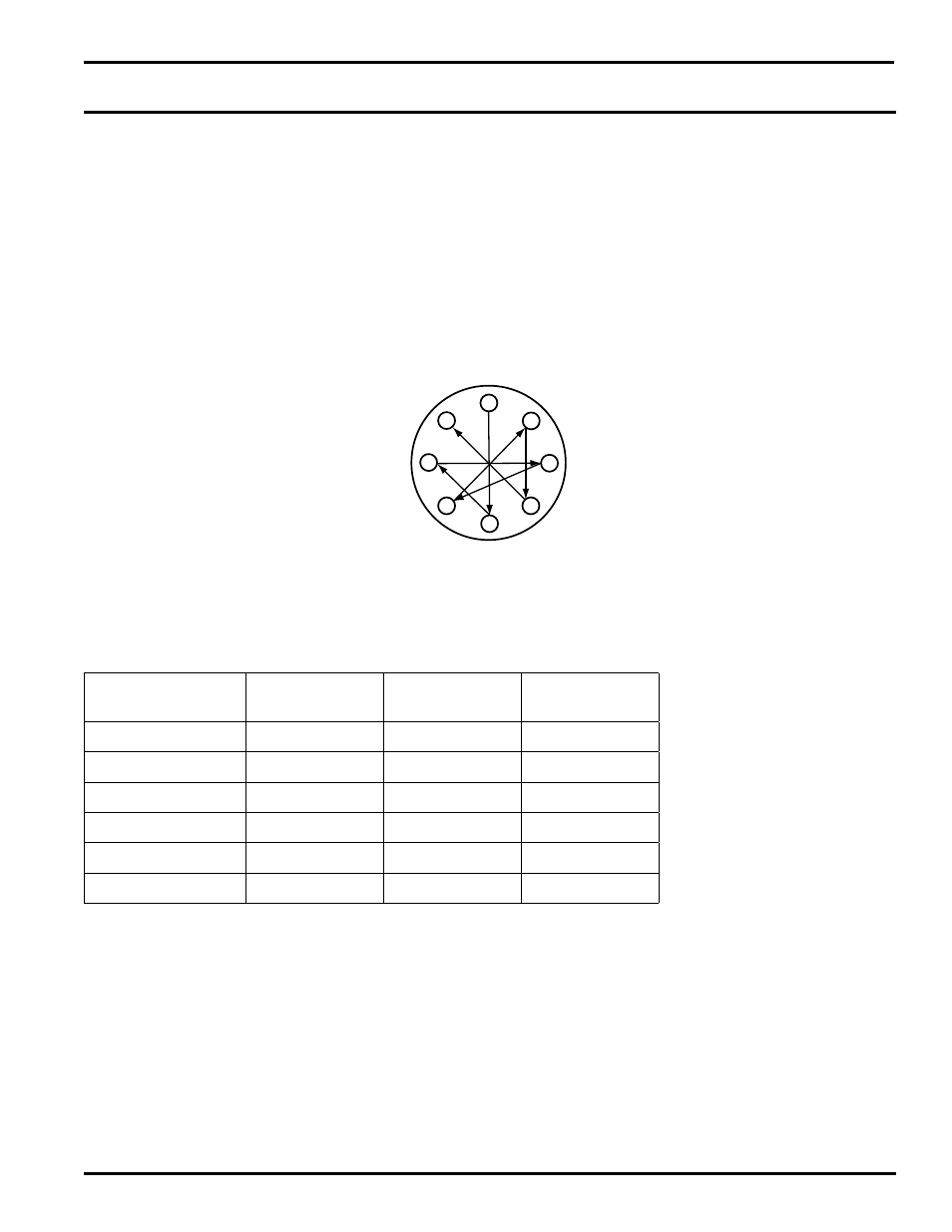
Ensure that an appropriate gasket is used between the flange mounting faces and when tightening the flange mounting
bolts to the process isolation valve, please ensure that the correct torque is applied (typically 100 foot pounds for a 2”
300# flange). As with any flanged bolt tightening, ensure that the correct sequence of tightening is followed (typically as
shown below):
1
6
4
7
2
5
3
8
5.2 Fast Loop Line Size and Response Times
The following table may be used when estimating sample line sizes, response times and resultant pressure drop through
the line. These calculations are based on a typical ethylene cracked gas effluent sample and should be used for estimating
purposes only:
Sample Line Size
Stainless Tube
Sample Line
Length
Sample Flow
Rate Lts/min
Response Time
Seconds
¼”
200’
1.5
39
¼
200’
3
19
¼
200’
4.5
13
3
/
8
”
200’
1.5
108
3
/
8
”
200’
3
54
3
/
8
”
200’
4.5
34
5. INSTALLATION