Warning, Caution, Vi. programming – Yokogawa AC8 Calibration Units User Manual
Page 9: Vii. set-up procedures
9
IM 11M6D2-02E-A
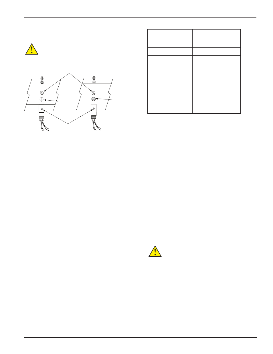
11. Turn the block solenoid and the
zero/span solenoid to
the
normal position.
WARNING
If reference air is used during calibration, the reference air must
remain ON after calibration.
NORMAL OPERATION
OVERRIDE
MOUNTING SCREW
FLOW ADJUSTMENT SCREW (PRESET)
FOR NORMAL
OPERATION THE
MANUAL
OVERRIDE SCREW
MUST BE IN THE
VERTICAL
POSITION
FOR OVERRIDE
THE MANUAL
OVERRIDE SCREW
MUST BE IN THE
HORIZONTAL
POSITION
Figure 5.3: Typical Channel Solenoid
5.4 CAL CHECK
The purpose of performing a cal check at this time is to con-
firm that the calibration gas and reference air are plumbed
correctly for each probe, along with confirming that enough
time was allowed for the cal gas to flow at the probe’s cell
tip. Refer to the AV550G Instruction Manual for calibration
codes and procedures.
VI. PROGRAMMING
All programming for the AV550G Averaging Unit is done
through the display module. Please refer to the AV550G
Instruction Manual, IM 11M12D01-01E, Section 9 for ad-
ditional details. The following is a brief description of setup
procedures.
The ZR22G Probe is calibrated by applying two known gas
standards. In most applications the zero gas is around 1%
oxygen with the balance nitrogen. The span gas is instru-
ment air (20.95 % oxygen).
The zero gas concentration must be certified so the exact
concentration can be programmed into the AV550G memory.
Calibration values required for full auto-calibration operations
are stored in the menu of the AV550G.
For additional information refer to Chapter 8 of the AV550G
manual for a full explanation of all parameters.
Shipping time default setting for zero gas is 1% oxygen and
for span gas is 21%. Figure 6.1
Item
Initial value
Mode
Manual
Points
Span-Zero
Zero gas conc.
1.00%
Span gas con.
21.00%
Hold time
3 min. 00 sec.
Cal. time
3 min. 00 sec.
Interval
1 days 00 hrs
Starting date
yy01mm01dd01
Starting time
hh00mm00
Figure 6.1
VII. SET-UP PROCEDURES
7.1 Mode
There are three calibration modes (for zero and span calibra-
tion: manual mode, semi-automatic mode (started from the
display or started by contact input) using preset calibration
time and stabilization (settling) time, and auto calibration
at preset intervals. Restrictions related to each mode are
described here.
-When [Manual Mode] is selected:
In this mode, only Manual calibration can be performed.
(Contact input used to start semi-auto calibration has no ef-
fect). Auto calibration does not start at auto calibration start
time.
-When [Semi-Auto Mode] is selected:
In this mode, manual calibration or semi-automatic
calibration can be performed.
Auto calibration does not start at auto calibration
start time.
-When [Auto Mode] is selected:
Any calibration mode is valid.
CAUTION
Indication check mode of [Auto] cannot coexist with [Auto]
Calibration mode. Therefore, if the mode of indication Check is
set to [Auto], you cannot set the mode of Calibration to [Auto],
and vice versa.
the [Execution/Setup] display appears. Select [Maintenance].
2) From the [Maintenance] display, select [CalibrationSetup]
the [Mode] amd you can selct Manual, Semi-Auto, or Auto in
the selection drop down that appears. Figure 7.1.