Warning – Yokogawa AC8 Calibration Units User Manual
Page 8
8
IM 11M6D2-02E-A
5.3 BALANCING PRESSURE DROPS IN THE CAL LINES
For accurate calibrations, the auto cal system must provide a
fixed flow of zero gas and span gas (0.6 LPM pr 600cc/min).
To do this, the pressure drop from the AC4/AC8 to each
probe must be the same regardless of the length of tubing
run or number of probes. To balance the pressure drops,
perform the following steps:
NOTE
Perform all adjustments with a flat tip screwdriver.
1. Ensure gas and instrument air are plumbed to the auto cal
unit. Pressure should be set at 20 psig ± 2 psig.
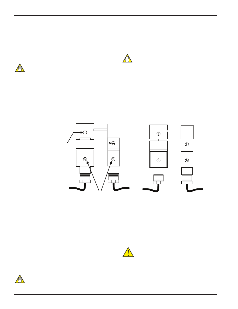
2. Locate the block solenoid shown in Figures 5.1 and 5.3.
Using a flat tip screwdriver, turn the manual override screw
on the block solenoid to the vertical position, as shown in
Figure 5.2.
ZERO/SPAN
SOLENOID
BLOCK
SOLENOID
MOUNTING
SCREWS
NORMAL
FOR NORMAL OPERATION AND
MANUAL OVERIDE, SCREWS
MUST BE IN THE POSITIONS
SHOWN
ZERO/SPAN
SOLENOID
BLOCK
SOLENOID
OVERRIDE
Figure 5.2: Zero and Block Solenoid
3. Locate the
cal gas flow meter in Figure 5.1. Turn the
black adjuster knob to the maximum open position. This fully
opens the cal gas regulator, allowing precise adjustments of
flow rates.
4. Locate the
channel solenoid valve for the probe with the
longest tubing run in Figure 5.1. Turn the manual override
screw to the horizontal, or ON position. Refer to Figure 5.3.
5. Each channel has its own flow adjustment screw located
on the
channel solenoid valve as shown in Figure 5.3. Ad-
just the flow adjustment screw for the probe so that the flow
rate shown on the cal gas flow meter is 1 LPM (1000 cc/min).
NOTE
DO NOT use the cal gas flow meter’s adjustment knob to make
this flow rate adjustment. If necessary, increase the air pres-
sure.
6. Turn the manual override on the channel solenoid for the
probe to the
OFF (normal) position.
7. Repeat steps 4, 5, and 6 for the remainder of the probes
that are being used.
NOTE
DO NOT use the cal gas flow meter’s adjustment knob to make
this flow rate adjustment. Use the individual channel’s flow
adjustment screw to adjust for varying pressure drops in the
tubing runs.
8. After all flow rates have been set manually to 1 LPM, turn
the channel solenoid for the probe with the longest tubing
run back ON to the manual override position – making sure
all others are
OFF (normal position shown in Figure 5.3). Turn
the cal gas flow meter’s adjustment knob to 0.6 LPM (600cc/
min).
9. Turn the
manual override screw (Figure 5.3) on the zero/
span solenoid (three way solenoid) to the 90º position. This
starts the flow of the zero gas. Adjust the
needle valve to
the left of the three-way solenoid so that the flow rate is 0.6
LPM (600cc/min). If 0.6 LPM is difficult to obtain, it will be
necessary to slightly increase the zero gas pressure to the
unit.
WARNING
Do not adjust the cal gas flow meter or the flow adjustment
screw on the individual channel solenoids.
10. Confirm that all
channel solenoid overrides for all used
probed are turned back to the normal position as shown in
Figure 5.3.