Important, Wmime?u – Yokogawa AC8 Calibration Units User Manual
Page 5
5
IM 11M6D2-02E-A
3.4 PIPING
PCDE?Q
A?J
E?Q
/-2ĥ
DCK?JCLNR
/-2ĥ
DCK?JCLNR
WMIME?U?
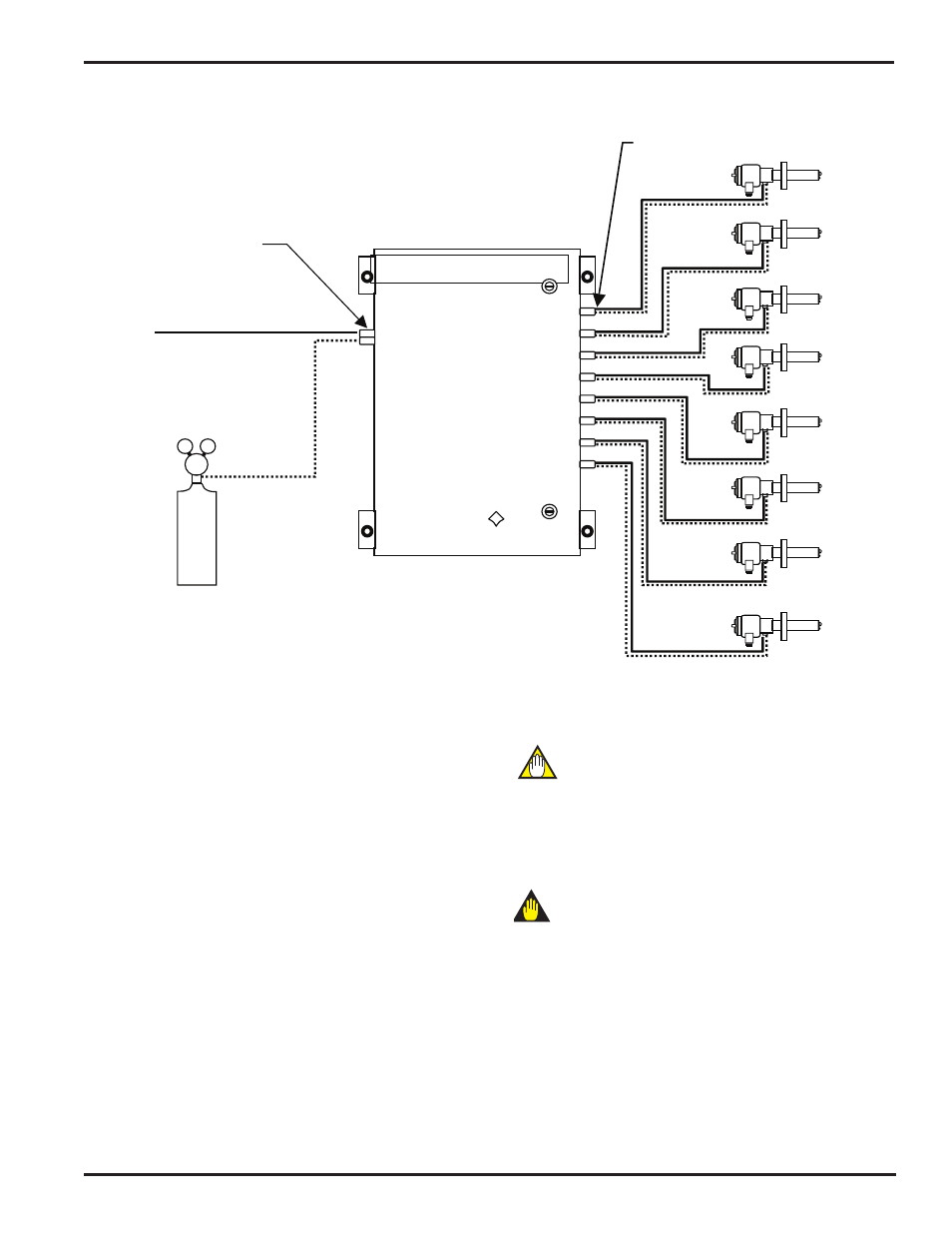
O2 CALIBRATION SYSTEM
LCK?2V
INSTRUMENT AIR
ZERO GAS
35 psig MAX
PROBE 1
PROBE 2
PROBE 3
PROBE 4
PROBE 5
PROBE 6
PROBE 7
PROBE 8
Figure 3.2
Piping Gases to the Auto Cal Unit
Piping (or tubing) is required from the instrument air line and
zero gas cylinder to the calibration unit. Standard tubing is _”
O.D. (Outside Diameter) copper or stainless steel. Stainless
steel is preferred, as it is less likely to develop leaks. The
separate tubing for both the instrument air and zero gas are
connected to the two separate 1/4” FNPT brass or stainless
fittings on the
LEFT side of the calibration unit.
Piping Gases to ZR22 Probes
The tubing to the ZR22 probes is run from the
RIGHT side of
the calibration unit to each of the ZR22 probes as shown in
Figure 2. Quarter inch (1/4”) tubing should be used between
the auto cal unit and the probes. It is important to note
1)
the reference air tubing is connected to the REF IN port
at the probe; 2) cal gas tubing is connected to the CAL
IN port on the probe. The REF IN and CAL GAS ports are
located on the bottom of the ZR22 probe junction box. The
check gas and reference air ports require a 1/4” FNPT fitting.
NOTE
Flexible stainless steel hose is recommended for the connection
between the ZR22 and the tubing.
This will allow for probe movement due to thermal expansion of
the duct.
IMPORTANT
To prevent leakage, all compression fittings should be installed
per manufacturer’s recommendations. In addition to this, a
check valve is usually installed on the cal gas inlet of the ZR22
probe to protect the cal tubing from moisture contamination.