4 <3 installation and wiring – Yokogawa Extractive Oxygen Gas Analyzer TDLS220 User Manual
Page 14
IM 11Y01B02-11E-A 3rd Edition :August 14, 2012-00
3-4
<3 INSTALLATION AND WIRING>
6
Factory
1
Ethernet
+ Transmit
2
- Transmit
3
+ Receive
4
- Receive
7
Factory
1-8
Detect
Internal connections only – do not use
8
Field
Analog
#1 output
+
Cal/Val initiate signal loop (SV # 1) to Remote voltage free con-
tacts/switch. Do not apply external power!
-
Analog
#2 output
+
Cal/Val initiate signal loop (SV # 2) to Remote voltage free con-
tacts/switch. Do not apply external power!
-
Analog
#3 output
+
Cal/Val initiate signal loop (SV # 2) to Remote voltage free con-
tacts/switch. Do not apply external power!
-
9
Factory
and/or
Field
1
Gas
Temperature
Compensation
Externally powered 4-20 mA gas temperature signals are wired to
1 (+) and 2(-), 3 not used.
Loop powered temperature transmitter can be connected to 1 (-)
and 3 (+24 VDC), 2 not used
2
3
4
Gas
Pressure
Compensation
Externally powered 4-20 mA gas pressure signals are wired to 1
(+) and 2(-), 3 not used.
Loop powered pressure transmitter can be connected to 1 (-) and
3 (+24 VDC), 2 not used
5
6
14
Factory
1-4
Mini-Display
Internal connections only – do not use
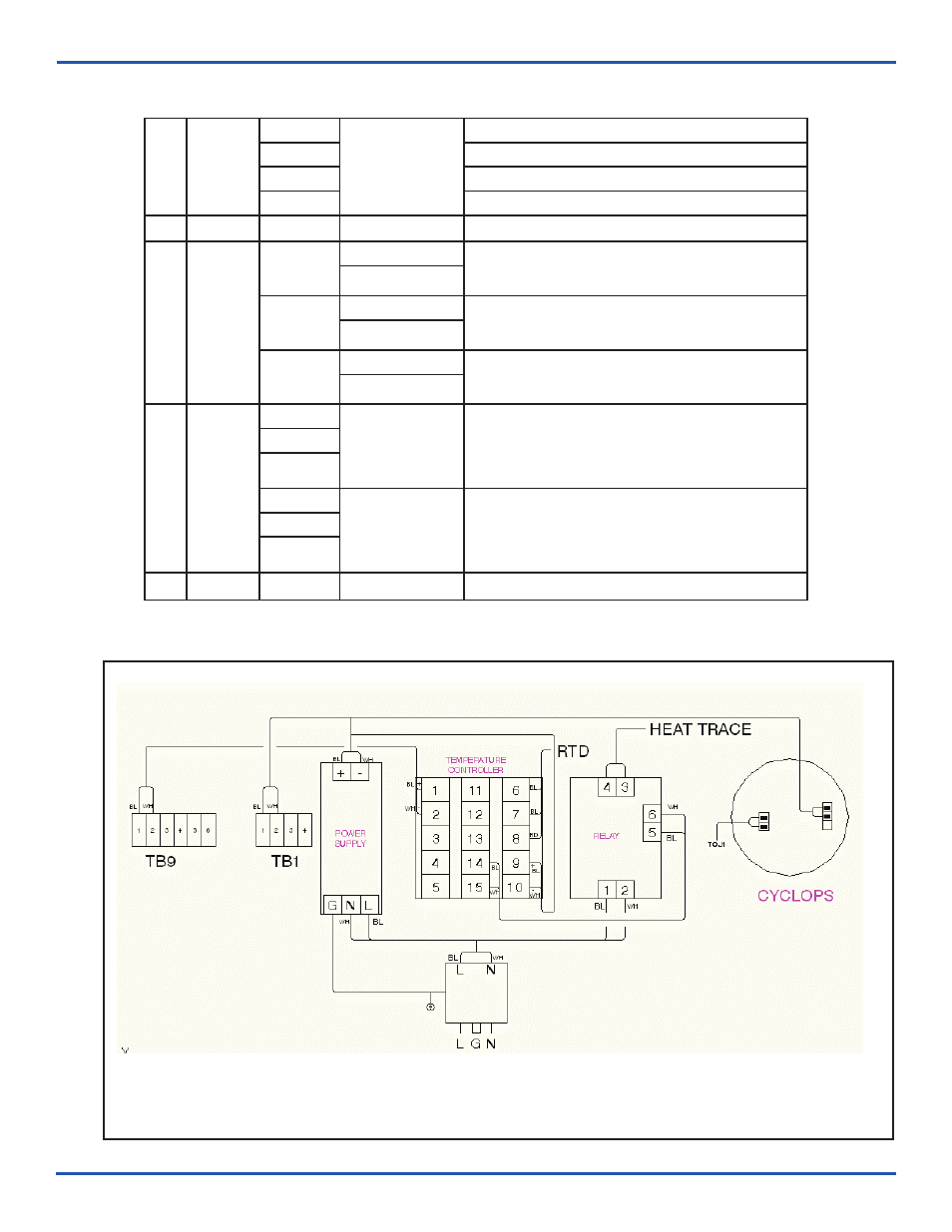
Figure 2 – Internal Wiring Diagram, including optional cell heating and optional purge unit