Model ej 120 – Yokogawa EJA310E User Manual
Page 73
<9. General Specifications>
9-25
IM 01C25B01-01E
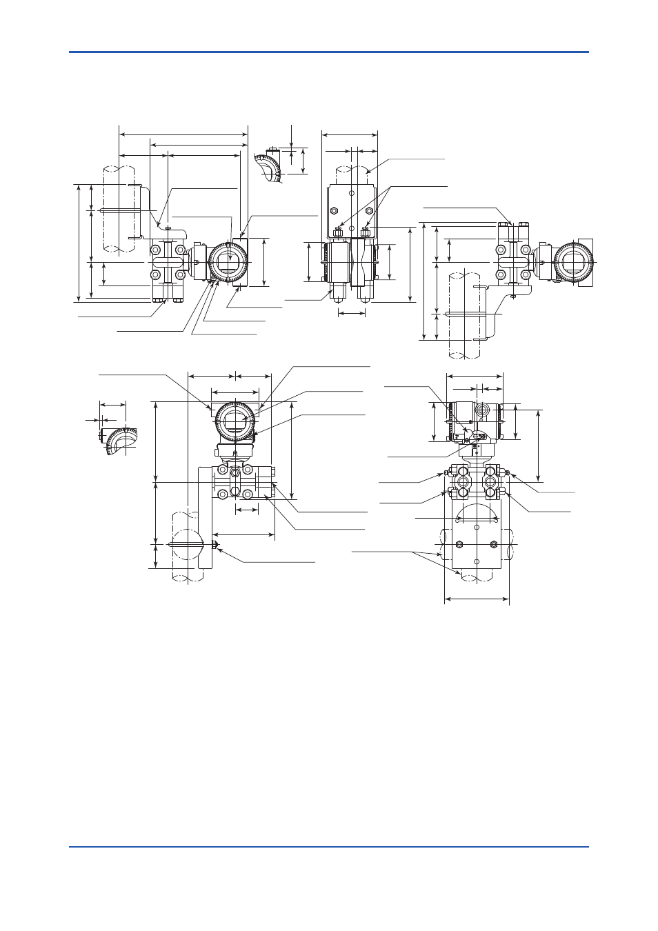
Model EJ120
Unit: mm (approx. inch)
54
(2.13)
6
(0.24)
Electrical connection
for code 5, 9, A, and D.
Process connection
72(2.83)
102(4.0
2)
234(9.21)
52
(2.05)
46
(1.81)
Electrical connection
for code 5, 9, A, and D.
54
(2.13)
6
(0.24)
● Horizontal Impulse Piping Type
(Installation code 9)
*1: When Installation code 2, 3, or 8 is selected, high and low pressure side on the above figure
are reversed. (i.e. High pressure side is on the right side.)
*2: When Option code K1, K2, K5, or K6 is selected, add 15 mm(0.59 inch) to the value in the figure.
*3: When Option code K1, K2, K5, or K6 is selected, add 30 mm(1.18 inch) to the value in the figure.
*4: Available only when specifying the option code including ATEX, IECEx or TIIS flameproof type.
● Vertical Impulse Piping Type
Integral indicator
(optional)
Extenal indicator
Conduit connection
(optional)
Mounting bracket
(Flat-type,optional)
Process connection
Conduit connection
72(2.83)
94(3.70)
124(4.88)
159(6.26)
47
(1.85)
194(7.64)
125(4.92)
46
(1.81)
95(3.75)
Ground terminal
Zero
adjustment
Vent plug
2-inch pipe
(O.D. 60.5 mm)
Drain plug
143(5.63)
128
*3
(5.04)
54
(2.13)
ш78(3.07)
ш70 (2.76)
39
(1.54)
110(4.33)
12
(0.47)
Vent plug
Drain plug
Shrouding bolt*
4
Vent/Drain plugs
2-inch pipe
(O.D. 60.5 mm)
148(5.83)
*2
54
(2.13)
12
(0.47)
110(4.33)
ш78(3.07)
ш70 (2.76)
39
(1.54)
Process connection
Mounting bracket
(L-type,optional)
Conduit
connection
Integral indicator
(optional)
Extenal indicator
Conduit connection
(optional)
72(2.83)
102(4.0
2)
234(9.21)
52
(2.05)
256(10.10)
143(5.63)
194(7.64)
97
(3.82)
95
(3.74)
46
(1.81)
Zero adjustment
Ground terminal
Shrouding bolt*
4
High
pressure
side
*1
Low
pressure
side
*1
Process
connector
(optional)
Process connector
(optional)
Process connector downside
(Installation code 7)
Process connector upside
(Installation code 6)
High
pressure
side
*1
Low
pressure
side
*1
F0908.ai