Model eja118y – Yokogawa EJA118 User Manual
Page 58
IM 1C22H1-01E
9-5
9. GENERAL SPECIFICATIONS
᭹
Model EJA118Y
[Style: S2]
. . . . . . . . . . . . . . . . . . . . . . . . . . . . . . . . . . .
-D . . . . . . . . . . . . . . . . . . . . . . . . . . . . . . . .
-E . . . . . . . . . . . . . . . . . . . . . . . . . . . . . . . .
-F . . . . . . . . . . . . . . . . . . . . . . . . . . . . . . . .
M . . . . . . . . . . . . . . . . . . . . . . . . . . . . . .
H . . . . . . . . . . . . . . . . . . . . . . . . . . . . . .
S . . . . . . . . . . . . . . . . . . . . . . . . . . . . .
J1 . . . . . . . . . . . . . . . . . . . . . . . . . .
J2 . . . . . . . . . . . . . . . . . . . . . . . . . .
A1 . . . . . . . . . . . . . . . . . . . . . . . . . .
A2 . . . . . . . . . . . . . . . . . . . . . . . . . .
P1 . . . . . . . . . . . . . . . . . . . . . . . . . .
P2 . . . . . . . . . . . . . . . . . . . . . . . . . .
D2 . . . . . . . . . . . . . . . . . . . . . . . . . .
D4 . . . . . . . . . . . . . . . . . . . . . . . . . .
2 . . . . . . . . . . . . . . . . . . . . . . . . .
4 . . . . . . . . . . . . . . . . . . . . . . . . .
6 . . . . . . . . . . . . . . . . . . . . . . . . .
P . . . . . . . . . . . . . . . . . . . . . . .
Q . . . . . . . . . . . . . . . . . . . . . . .
R . . . . . . . . . . . . . . . . . . . . . . .
A . . . . . . . . . . . . . . . . . . . . .
B . . . . . . . . . . . . . . . . . . . . .
-A . . . . . . . . . . . . . . . . .
-B . . . . . . . . . . . . . . . . .
-C . . . . . . . . . . . . . . . . .
-D . . . . . . . . . . . . . . . . .
-E . . . . . . . . . . . . . . . . .
C . . . . . . . . . . . . . . . .
ᮀ ᮀ
. . . . . . . . . . .
-9 . . . . . . . . . . . .
0 . . . . . . . . . . .
2 . . . . . . . . . . .
3 . . . . . . . . . . .
4 . . . . . . . . . . .
5 . . . . . . . . . . .
7 . . . . . . . . . . .
8 . . . . . . . . . . .
9 . . . . . . . . . . .
D . . . . . . . . .
E . . . . . . . . .
N . . . . . . . . .
A . . . . . . .
B . . . . . . .
N . . . . . . .
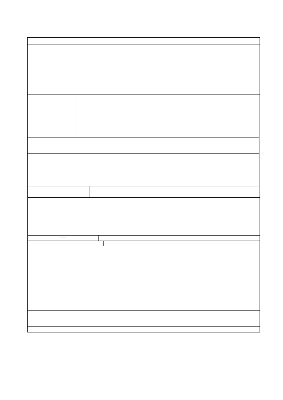
Model
Suffix Codes
Description
EJA118Y
Output Signal
Measurement span
(capsule)
High pressure side wetted
(extended diaphragmtype)
parts material
(Note 2)
Process flange rating
Diaphragm extension
length (X
2
)
Process flange size / material
Cover flange bolts material
Fill fluid
Capillary length (m)
Installation
Electrical connection
Integral indicator
Mounting bracket
Optional codes
Diaphragm sealed differential pressure transmitter
(Combination of extended diaphragm and flush diaphragm type)
4 to 20 mA DC with digital communication (BRAIN protocol)
4 to 20 mA DC with digital communication (HART protocol)
(Note 1)
Digital communication (FOUNDATION Fieldbus protocol)
(Note 3)
2.5 to 100 kPa {250 to 10000 mmH
2
O}
25 to 500 kPa {0.25 to 5 kgf/cm
2
}
[Diaphragm]
[Pipe]
[Others]
JIS SUS316L
JIS SUS316
JIS SUS316
JIS 10K
JIS 20K
ANSI class 150
ANSI class 300
JPI class 150
JPI class 300
DIN PN10/16
DIN PN25/40
X
2
= 50 mm
X
2
= 100 mm
X
2
= 150 mm
High pressure side 4-inch (100 mm) / JIS S25C
Low pressure side 3-inch (80 mm) / JIS S25C
High pressure side 4-inch (100 mm) / JIS SUS304
Low pressure side 3-inch (80 mm) / JIS SUS304
High pressure side 4-inch (100 mm) / JIS SUS316
Low pressure side 3-inch (80 mm) / JIS SUS316
JIS SCM435
JIS SUS630
[Process
[Ambient
temp.]
temp.]
For general use (silicone oil)
–10 to 250
Њ
C –10 to 60
Њ
C
For general use (silicone oil)
–30 to 180
Њ
C –15 to 60
Њ
C
For high temperature use (silicone oil)
10 to 300
Њ
C
10 to 60
Њ
C
For oil-prohibited use (fluorinated oil)
–20 to 120
Њ
C –10 to 60
Њ
C
For low temperature use (ethylene glycol)–50 to 100
Њ
C –40 to 60
Њ
C
Always C
Specify capillary length from 1 to 10 m in
ᮀ ᮀ
. (Example for 2 m: 02)
Horizontal impulse piping type, left side high pressure
G1/2 female, one electrical connection
1/2 NPT female, two electrical connections without blind plug
PG 13.5 female, two electrical connections without blind plug
M20 female, two electrical connections without blind plug
G1/2 female, two electrical connections and a blind plug
1/2 NPT female, two electrical connections and a blind plug
PG 13.5 female, two electrical connections and a blind plug
M20 female, two electrical connections and a blind plug
Digital indicator
Digital indicator with the range setting switch
(None)
JIS SECC
2-inch pipe mounting (flat type)
JIS SUS304
2-inch pipe mounting (flat type)
(None)
/
ᮀ
Optional specification
T0906.EPS
Example: EJA118Y-DMSA12PA-AC02-92NA/
ᮀ
Note 1: Refer to GS 1C22T1-E for HART Protocol version.
Note 2: Low pressure side (Flush diaphragm) wetted parts material: Diaphragm and others; SUS316L.
Note 3: Refer to GS 1C22T2-E for Fieldbus communication.