General specifications, 1 standard specifications – Yokogawa EJA118 User Manual
Page 54
IM 1C22H1-01E
9-1
9. GENERAL SPECIFICATIONS
9.
GENERAL SPECIFICATIONS
9.1
Standard Specifications
Refer to GS 1C22T2-E for Fieldbus communica-
tion type marked with “
᭛
”.
᭹
Performance Specifications
See General Specifications sheet, GS 1C22H1-E.
᭹
Functional Specifications
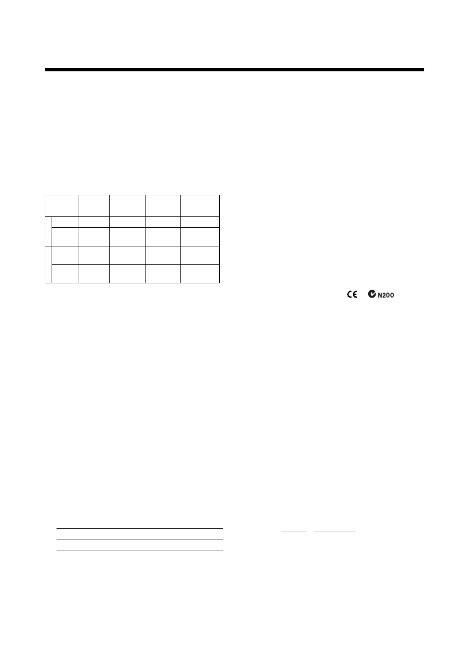
Span & Range Limits
M
Measurement
Span
and Range
Span
Range
inH
2
O
(/D1)
10 to 400
–400 to
400
mbar
(/D3)
mmH
2
O
(/D4)
25 to 1000
–1000 to
1000
250 to 10000
–10000 to
10000
kPa
2.5 to 100
–100 to
100
H
Span
Range
100 to 2000
–2000 to
2000
250 to 5000
–5000 to
5000
0.25 to
5 kgf/cm
2
–5 to
5 kgf/cm
2
25 to 500
–500 to
500
T0901.EPS
URL is define as the Upper Range Limit from the table
above.
Zero Adjustment Limits:
Zero can be fully elevated or suppressed, within
the Lower and Upper Range Limits of the capsule.
External Zero Adjustment “
᭛
”:
External zero is continuously adjustable with
0.01% incremental resolution of span. Span may
be adjusted locally using the digital indicator with
range switch.
Output “
᭛
”:-
Two wire 4 to 20 mA DC output with digital
communications, linear or square root program-
mable. BRAIN or HART FSK protocol are superim-
posed on the 4 to 20 mA signal.
Failure Alarm:
Output status at CPU failure and hardware error;
Up-scale: 110%, 21.6 mA DC or more (standard)
Down-scale: –5%, 3.2 mA DC
Note: Applicable for Output signal code D and E
Damping Time Constant (1st order):
The sum of the amplifier and capsule damping
time constant must be used for the overall time
constant. Amp damping time constant is adjustable
from 0.2 to 64 seconds.
Time Constant (approx. sec)
1.5
1.0
M
H
T0902.EPS
Capsule (Silicone Oil)
When the capillary length 3 m and the fill fluid code
A.
Ambient Temperature Limits:
* Safety approval codes may affect limits.
–40 to 60
°
C (–40 to 140
°
F)
–30 to 60
°
C (–22 to 140
°
F) with LCD Display
Note: The ambient temperature limits must be within
the fill fluid operating temperature range, see
Table 1.
Process Temperature Limits:
* Safety approval codes may affect limits.
See Table 1.
Working Pressure Range:
2.7 kPa {20 mmHg abs} to flange rating pressure.
For atmospheric pressure or below, see Figure 1.
᭹
Installation
Supply & Load Requirements “
᭛
”:
* Safety approvals can affect electrical requirements.
See Section 5.6, ‘Power Supply Voltage and Load
Resistance.’
EMC Conformity Standards:
,
For EMI (Emission): EN55011, AS/NZS 2064 1/2
For EMS (Immunity): EN50082-2
Communication Requirements “
᭛
”:
BRAIN
Communication Distance;
Up to 2 km (1.25 miles) when using CEV polyethyl-
ene-insulated PVC-sheathed cables.
Communication distance varies depending on type
of cable used.
Load Capacitance;
0.22
µ
F or less (see note)
Load Inductance;
3.3 mH or less (see note)
Input Impedance of communicating device;
10 k
Ω
or more at 2.4 kHz.
Note: For general-use and Flameproof type.
For Intrinsically safe type, please refer to
‘Optional Specifications.’
HART
Communication Distance;
Up to 1.5 km (1 mile) when using multiple twisted
pair cables. Communication distance varies
depending on type of cable used.
Use the following formula to determine cable
length for specific applications:
L=
-
65 x 10
6
(R x C)
(C
f
+ 10,000)
C
Where:
L = length in meters or feet
R = resistance in
Ω
(including barrier resistance)
C = cable capacitance in pF/m or pF/ft
C
f
= maximum shunt capacitance of receiving
devices in pF/m or pF/ft