Installation, 1 precautions, 2 mounting the diaphragm seals – Yokogawa EJA118 User Manual
Page 19
IM 1C22H1-01E
4-1
4. INSTALLATION
4.
INSTALLATION
4.1 Precautions
Before installing the transmitter, read the cautionary
notes in Section 2.4, “Selecting the Installation
Location.” For additional information on the
ambient conditions allowed at the installation
location, refer to Subsection 9.1 “Standard Specifi-
cations.”
IMPORTANT
• When welding piping during construction, take
care not to allow welding currents to flow
through the transmitter.
• Do not step on this instrument after installation.
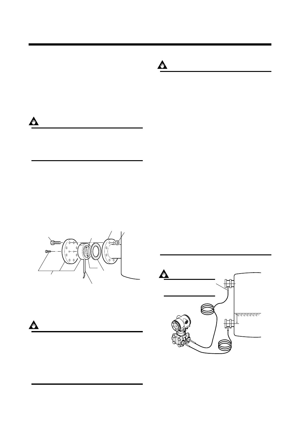
4.2 Mounting the Diaphragm
Seals
Mount the diaphragm seals using the flanges as shown
in Figure 4.2.1. Figure 4.2.2 shows how to mount the
diaphragm seals on a tank. The customer should
prepare the mating flange, gasket, bolts and nuts.
Nut
Flange
Diaphragm
ød
Gasket
F0401.EPS
Bolt
The product is shipped with
these parts assembled.
Correctly install the diaphragm seals on
the high and low pressure sides of the
process, checking the label on each seal.
Figure 4.2.1 Mounting the Diaphragm Seals
IMPORTANT
Please use a gasket which has a bigger inside
diameter than that of gasket facing (ød) on
diaphragm seal. In case a gasket which has a
smaller inside diameter than that of gasket
facing is used, it may cause an error as the
gasket prevents diaphragm from working cor-
rectly. (Refer to Subsection 9.4 ‘Dimensions’)
IMPORTANT
• When measuring the liquid level of the tank,
the minimum liquid level (zero point) must be
set to a level at least 50 mm above the center
of the high pressure side diaphragm seal (see
Figure 4.2.2).
• Correctly install the diaphragm seals on the
high and low pressure sides of the process,
checking the label on each seal.
• To avoid measuring error duets temperature
difference between the two diaphragm seals,
capillary tube must be bound together. The
capillary tube must be securely fixed to the
tank wall to prevent movement by wind or
vibration. If the capillary tube are too long,
loosely coil the excess and secure using
suitable clamps.
• During the diaphragm seal installation, ensure
as far as possible that no seal liquid head is
applied to the diaphragm seals.
• Exercise care so as not to damage diaphragm
surfaces. Since the diaphragm protrudes
approx. 1mm from the flange surface, placing
the diaphragm seals with their diaphragm
surfaces facing downward may damage the
diaphragm surfaces.
• Do not sharply bend or twist capillary tube or
apply excessive stress to them.
F0402.EPS
Low
pressure
side
High
pressure
side
50mm minimum
Minimum
liquid level
The transmitter should be installed as low
as possible below the position where the
high pressure side diaphragm seal is
installed.
IMPORTANT
Install the sealed diaphragm
so that the shank positions
downward.
Figure 4.2.2 Installing the Diaphragm Seals to a Tank