3 transmitter mounting – Yokogawa EJA118 User Manual
Page 20
IM 1C22H1-01E
4-2
4. INSTALLATION
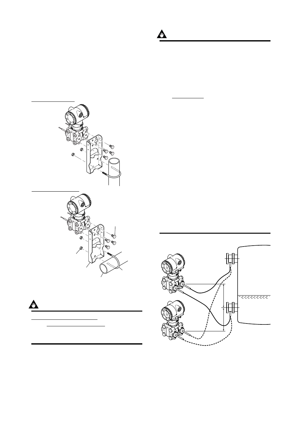
4.3 Transmitter Mounting
The transmitter can be mounted on a nominal 50
mm (2-inch) pipe using the mounting bracket
supplied, as shown in Figure 4.3.1. The transmitter
can be mounted on either a horizontal or a vertical
pipe.
When mounting the bracket on the transmitter,
tighten the (four) bolts that hold the transmitter to a
torque of approximately 39 N·m {4 kgf·m}.
Horizontal pipe mounting
Vertical pipe mounting
Transmitter
mounting bolt
U-bolt nut
Mounting bracket
50mm (2-inch) pipe
U-bolt
F0403.EPS
Figure 4.3.1 Transmitter Mounting
IMPORTANT
Never loosen the four screws securing the cover
flange or the screws at the joints between the
capillary tube and cover flanges (if the seal liquid
leaks, the transmitter cannot be used).
IMPORTANT
The transmitter should be installed at least 600
mm below the high pressure (HP) process
connection to ensure a positive head pressure of
fill fluid. Pay special attention to vacuum applica-
tions. If it can not be installed at least 600 mm
below the HP process connection, please use
the equation below:
h=
ϫ
7.5
ϫ
10
–3
[mm]
(P–P0)
ϫ
dHg
ds
h:
Vertical height between the HP process
connection and the transmitter (mm)
h
≤
0: Install the transmitter at least h (mm)
below the HP process connection
h>0: Install the transmitter at most h (mm)
above the HP process connection
P:
Pressure in the tank (Pa abs)
P0: Minimum working pressure limit of the
transmitter (Pa abs)
If the ambient temperature range is
–10 to 50
°
C.
3178 (Wetted parts material code S)
3596 (Wetted parts material code T)
6074 (Wetted parts material code H)
4711 (Wetted parts material code U)
ds: Specific gravity of fill fluid (at 25
°
C), refer
to GS 1C22H1-E.
dHg:Specific gravity of the Mercury 13.6
(at 25
°
C)
F0404.EPS
P
h
Low pressure side
0
High
pressure
side
(+)
(–)
Figure 4.3.2 Example of Installation to Tank (Caution on
Installation)