Wiring, 1 wiring precautions, 2 selecting the wiring materials – Yokogawa EJA118 User Manual
Page 22: 3 connections of external wiring to terminal box, 1 power supply wiring connection, 2 external indicator connection, 2 selecting the wiring materi- als
IM 1C22H1-01E
5-1
5. WIRING
5.
WIRING
5.1 Wiring Precautions
IMPORTANT
• Lay wiring as far as possible from electrical
noise sources such as large capacity transform-
ers, motors, and power supplies.
• Remove electrical connection dust cap before
wiring.
• All threaded parts must be treated with water-
proofing sealant. (A non-hardening silicone
group sealant is recommended.)
• To prevent noise pickup, do not pass signal
and power cables through the same ducts.
• Explosion-protected instruments must be wired
in accordance with specific requirements (and,
in certain countries, legal regulations) in order
to preserve the effectiveness of their explosion-
protected features.
• The terminal box cover is locked by an Allen
head bolt (a shrouding bolt) on CENELEC,
SAA, and JIS flameproof type transmitters.
When the shrouding bolt is driven clockwise by
an Allen wrench, it is going in and cover lock is
released, and then the cover can be opened.
See Subsection 8.4 “Disassembly and Reas-
sembly” for details.
Refer to The “Installation and Operating
Precautions for JIS Flameproof Equipment”
and “Installation and Operating Precautions
for JIS Intrinsically Safe Equipment” at the
end of this manual for correct wiring.
5.2 Selecting the Wiring Materi-
als
(a) Use stranded leadwires or cables which are the
same as or better than 600 V grade PVC insulated
wire (JIS C3307) or equivalent.
(b) Use shielded wires in areas that are susceptible to
electrical noise.
(c) In areas with higher or lower ambient temperatures,
use appropriate wires or cables.
CAUTION
If the transmitter is flameproof and the ambient
temperature is 50
°
C or more, use cables having
a maximum allowable heat resistance of at least
75
°
C in consideration of the instrument's genera-
tion of heat or the cables' self-heating.
(d) In environment where oils, solvents, corrosive gases
or liquids may be present, use wires or cables that
are resistant to such substances.
(e) It is recommended that crimp-on solderless terminal
lugs (for 4 mm screws) with insulating sleeves be
used for leadwire ends.
5.3 Connections of External
Wiring to Terminal Box
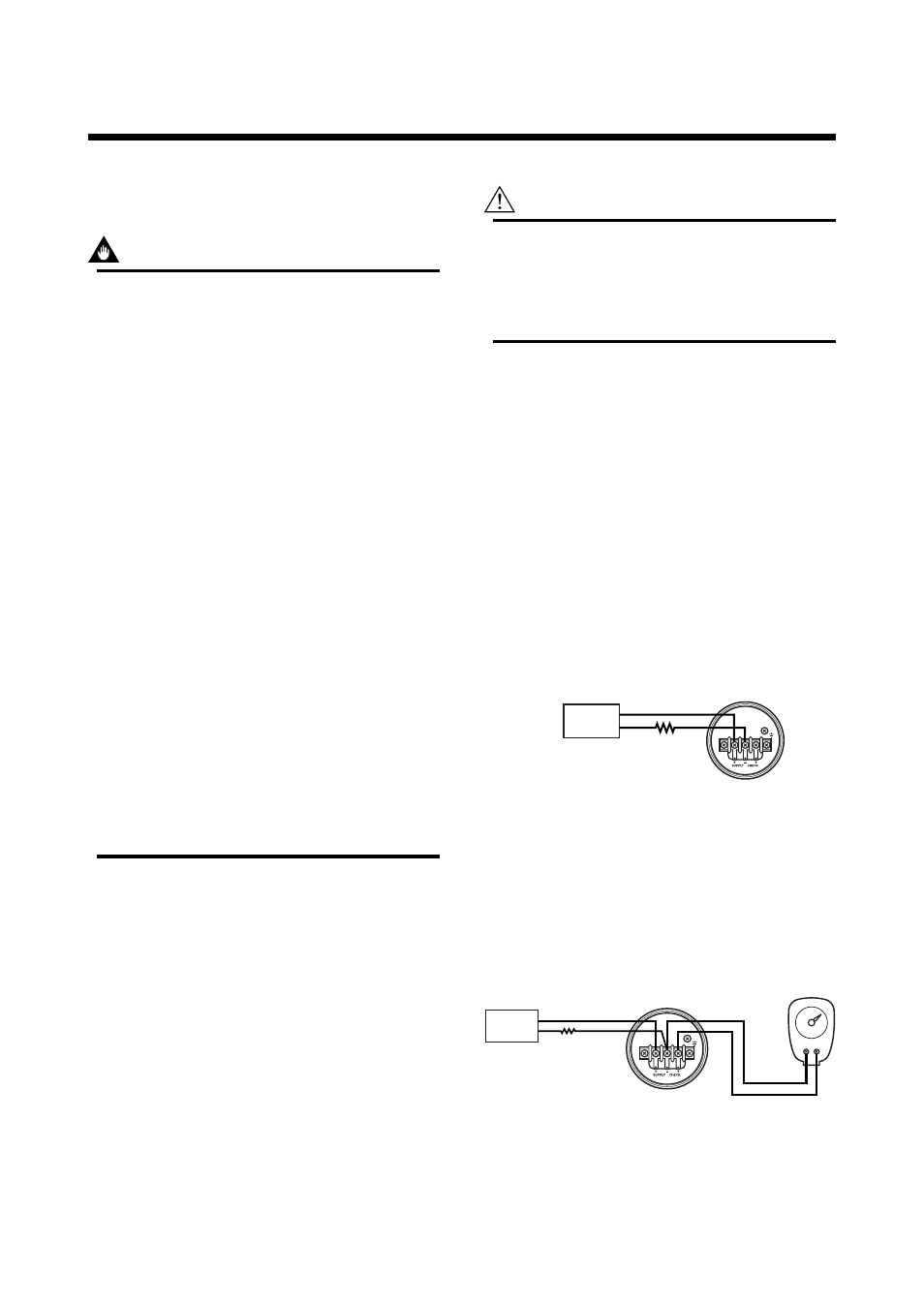
5.3.1 Power Supply Wiring Connection
Connect the power supply wiring to the SUPPLY +
and – terminals.
Power supply
–
+
Transmitter terminal box
F0501.EPS
Figure 5.3.1 Power Supply Wiring Connection
5.3.2 External Indicator Connection
Connect wiring for external indicators to the CHECK +
and – terminals.
(Note) Use a external indicator whose internal resistance is 10
Ω
or
less.
Transmitter terminal box
External indicator
F0502.EPS
Power supply
–
+
Figure 5.3.2 External Indicator Connection