2 troubleshooting flow charts, Troubleshooting flow charts -6 – Yokogawa EJA220A User Manual
Page 56
IM 01C21C01-01E
9-6
9. MAINTENANCE
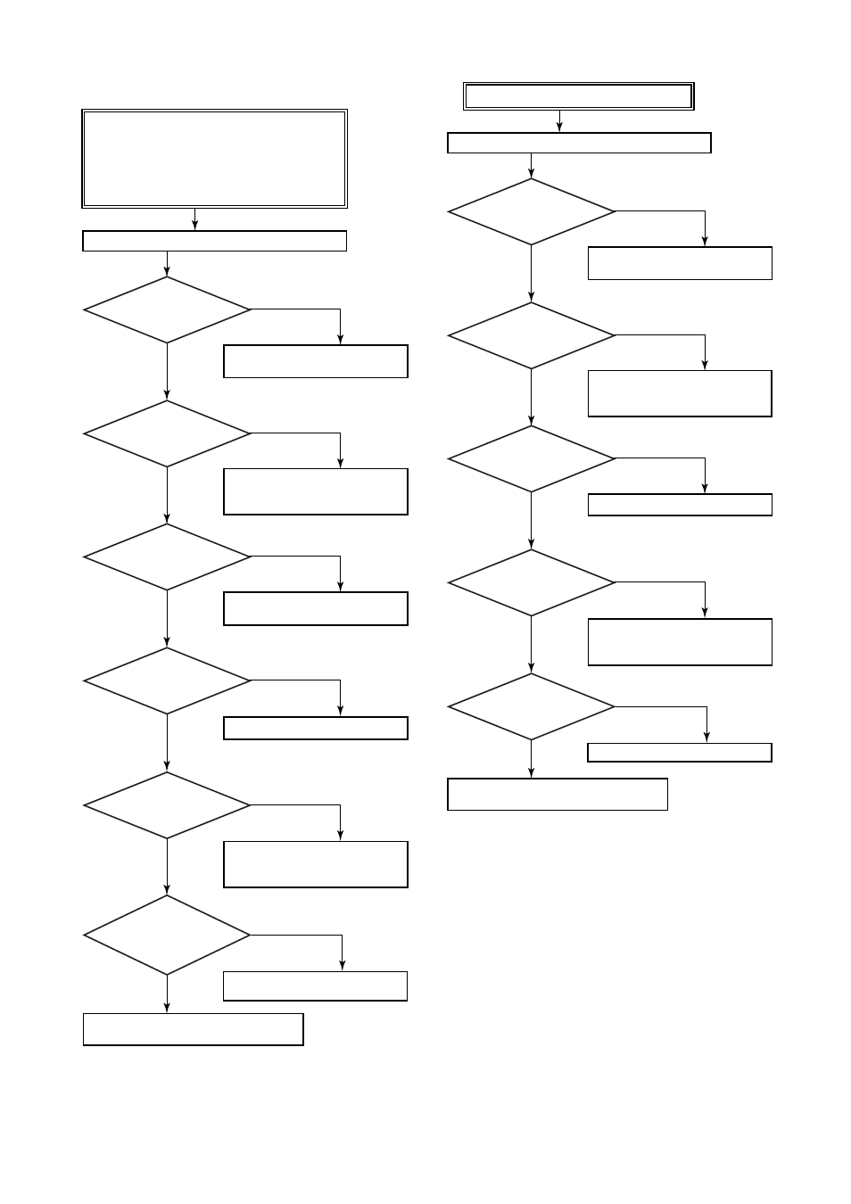
9.5.2 Troubleshooting Flow Charts
Connect BRAIN TERMINAL and check self-diagnostics.
Does the self-diagnostic
indicate problem location?
Contact Yokogawa service personnel.
F0906.EPS
The following sorts of symptoms indicate that transmitter
may not be operating properly.
Example : • There is no output signal.
• Output signal does not change even though
process variable is known to be varying.
• Output value is inconsistent with value
inferred for process variable.
Is power supply
polarity correct?
Are power
supply voltage and load
resistance correct?
Refer to error message summary in
Subsection 8.5.2 to take actions.
Refer to Section 6.3 to check/correct
polarity at each terminal from power
supply to the terminal box.
Fix pressure leaks, paying particular
attention to connections for impulse
piping, pressure-detector section, etc.
Fully open the low pressure valve.
Refer to Section 6.6 for rated voltage
and load resistance.
Find/correct broken conductor or
wiring error.
Are valves opened or
closed correctly?
Is there any pressure leak?
Is there
continuity through the
transmitter loop wiring?
Do the loop numbers
match?
YES
NO
YES
NO
NO
YES
NO
NO
YES
YES
NO
YES
Connect BRAIN TERMINAL and check self-diagnostics.
Does the self-
diagnostic indicate problem
location?
Contact Yokogawa service personnel.
F0907.EPS
Is power supply
polarity correct?
Are valves opened or
closed correctly?
Refer to error message summary in
Subsection 8.5.2 to take actions.
YES
NO
NO
YES
Refer to Section 6.3 to check/correct
polarity at each terminal from power
supply to the terminal box.
Fix pressure leaks, paying particular
attention to connections for impulse
piping, pressure-detector section, etc.
Fully open the low pressure valve.
NO
YES
YES
NO
Adjust the zero point.
NO
YES
Is there any pressure leak?
Is zero point
adjusted correctly?
Output travels beyond 0% or 100%.