4 changing the direction of integral indicator, 5 affixing the teflon film, Changing the direction of integral indicator -2 – Yokogawa EJA220A User Manual
Page 22: Affixing the teflon film -2
IM 01C21C01-01E
4-2
4. INSTALLATION
4.4 Changing the Direction of
Integral Indicator
IMPORTANT
Always turn OFF power, release pressure and
remove a transmitter to non-hazardous area
before disassembling and reassmbling an
indicator.
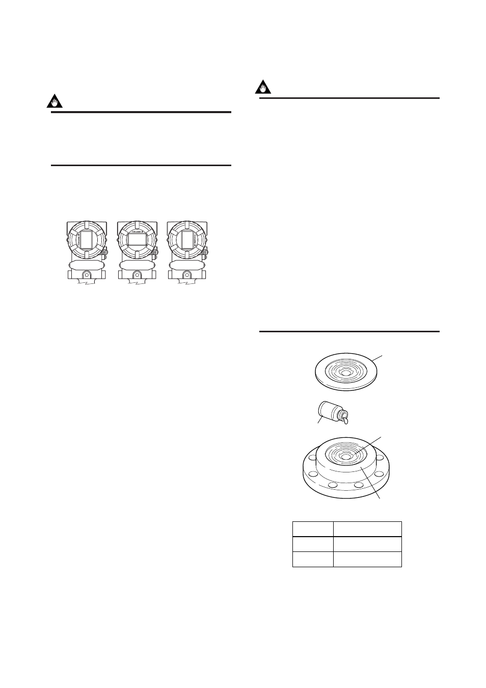
An integral indicator can be installed in the following
three directions. Follow the instructions in section 9.4
for removing and attaching the integral indicator.
F0404.EPS
Figure 4.3
Integral Indicator Direction
4.5 Affixing the Teflon Film
IMPORTANT
The FEP Teflon option includes a teflon film and
fluorinated oil. Before mounting the transmitter
to the process flange, affix the teflon film as
follows:
1) Position the diaphragm so that the diaphragm
is in a upward position.
2) Pour the fluorinated oil on the diaphragm and
gasket area covering it completely and evenly.
Be careful not to scratch the diaphragm or
change the its shape.
3) Affix the teflon film over the diaphragm and
gasket area.
4) Next, carefully inspect the cover and try to
identify any entrapped air between the dia-
phragm and the teflon film. The air must be
removed to ensure accuracy. If air pockets are
present, use your fingers to remove the air by
starting at the center of the diaphragm and
work your way out.
5) Place the gasket with the teflon film and affix
to the process flange.
Teflon film
Diaphragm
Fluorinated oil
[PART No. : F9145YN]
Gasket area
PART No.
F9347XA
F9347YD
Prosess Flange size
3 inch (80mm)
2 inch (50mm)
F0403.EPS
Figure 4.4 Affixing the Teflon Film