English – Pfister F-531-4TMS User Manual
Page 4
ENGLISH
ENGLISH
12
14
11
13
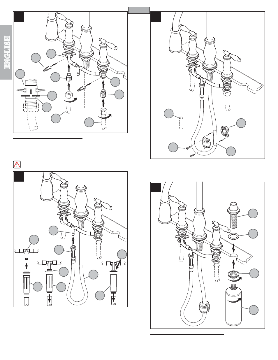
11 WATER SUPPLY CONNECTIONS
First, thread Inlet Connectors (11A) into Water Supply Lines (11B). Then, insert Inlet
Connectors (11A) into Valve Bodies (11C).
Hot water supply lines go into left inlet.
Cold water supply lines go into right inlet. (Supply lines not included). Please follow
manufacturer’s instructions when installing supply lines. Next, insert Clips (11D) into
Valve Body Holes (11E), to secure unit.
WARNING: Do not twist Inlet Connectors (11A) once installed!
12 PULL-OUT HOSE ATTACHMENT
From underneath sink, push Quick Connector (12A), located on the end of the Pull-Out
Hose (12B) firmly upward onto the Receiving Tube (12C), until unable to push any
further. Pull down on the Quick Connector (12A). If the housing and the Inner Collet
(12D) separate slightly but do not pull off, the Receiving Tube (12C), quick connect is
secure.
To remove Pull-Out Hose (12B), Push up on Quick Connector (12A). Holding Plastic
Collet (12D) in place, pull downward on Quick Connector (12A) until Tube (12C) is
free.
13 WEIGHT ATTACHMENT
Discard Cardboard Fitting (13B) from Weight (13A). Place Weight (13A) above the
beginning of hose bend (13C) at the spout side (as shown in shaded area). Secure
Weight (13A) with Screws (13D).
14 SOAP DISPENSER INSTALLATION
From above sink, insert threaded Shank (14A) of soap dispenser body through Foam
Gasket (14B) and sink hole. From below sink, tighten Nut (14C) and thread on Bottle
(14D) to Shank (14A).
4
HOT
COLD
11A
11C
11C
11D
11B
11E
11D
11C
11B
11A
12A
12D
12A
12A
12D
12A
12C
12B
12C
13B
13A
13C
13D
14A
14B
14C
14D