English, Faucet installation – Pfister F-531-4TMS User Manual
Page 2
ENGLISH
ENGLISH
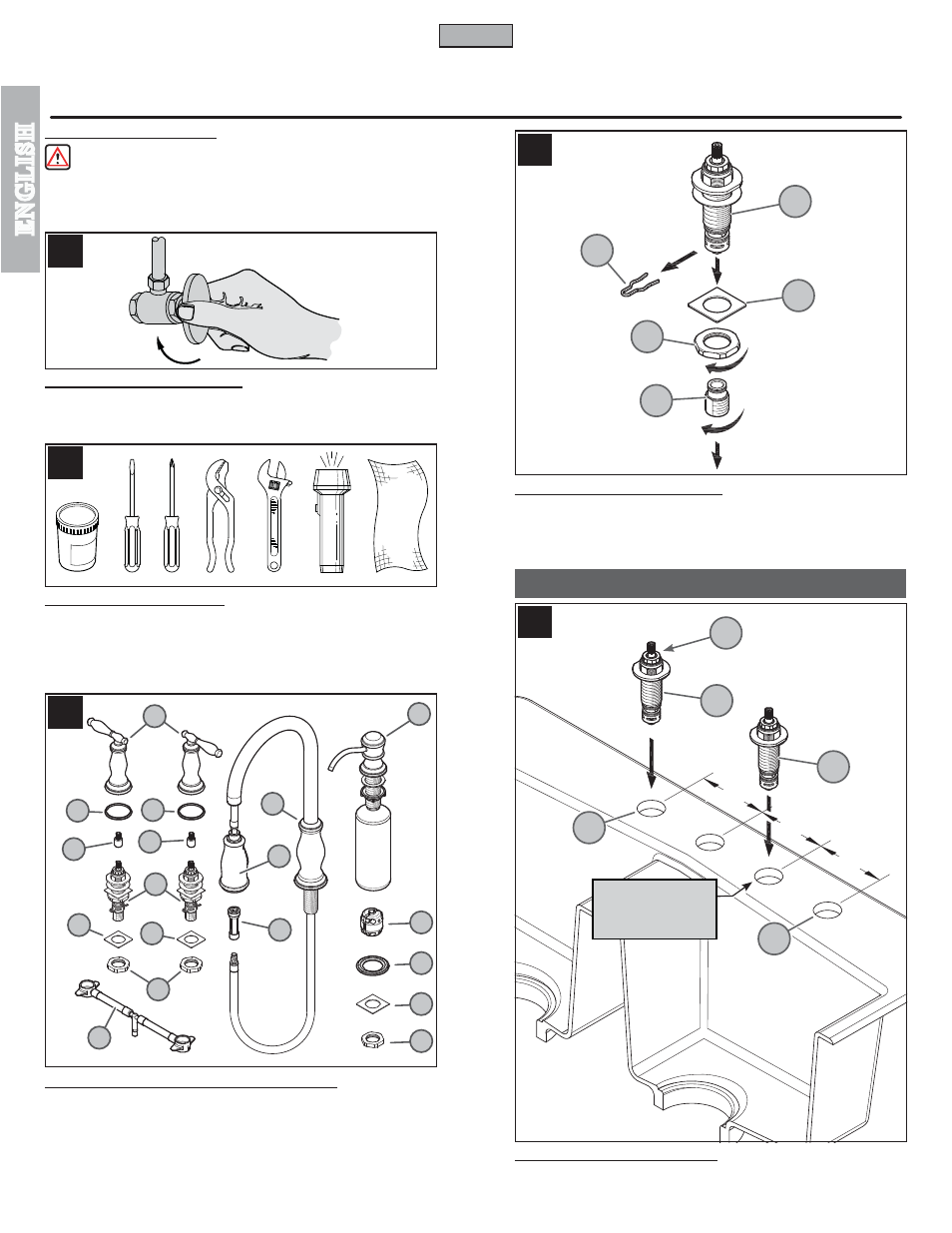
FAUCET INSTALLATION
4
2
5
6
3
Thank you for purchasing this Price Pfister product. All Price Pfister products are carefully engineered, and factory tested to
provide long trouble-free use under normal conditions. This product is easy to install using basic tools and our easy to follow
illustrated instructions. If you have any questions regarding this product, call 1-800-Pfaucet (1-800-732-8238).
1 BEFORE PROCEEDING
WARNING: Read all the instructions completely before proceeding. Price Pfister
recommends calling a professional if you are uncertain about installing this product!
This product should be installed in accordance with all local and state plumbing and
building codes.
2 SHUT OFF WATER SUPPLY
Locate water supply inlets and shut off the water supply valves. These are usually found
under the sink or near the water meter. If you are replacing an existing faucet, remove
the old faucet from the sink and clean the sink surface thoroughly.
3 TOOLS RECOMMENDED
• Plumber's putty
• Slotted screwdriver
• Philips head screwdriver
• Pliers
• Adjustable wrench
• Flashlight
• Cloth
Your installation may require new supply lines and / or shut-off valves or other additional
tools.
4 CHECKING THE CONTENTS OF THE BOX
Upon opening the box, check to ensure that all of the following items are included:
A Spout Body
B Valve Bodies (2X)
C Handles (2X)
D Spray Head
E Hose
F Putty Rings (3X)
G Square Washers (3X)
H Locknuts (3X)
J Soap Dispenser
K Weight
L Quick Connector
M Stem Extender
If any of these items are missing, please contact Price Pfister Consumer Services at
1-800-Pfaucet (1-800-732-8238).
5 VALVE BODY PREPARATION
First, remove Clip (5A) then remove Inlet Connector (5B) from Valve Bodies (5C) and
save. Next, remove Locknut (5D), and Square Washer (5E) from Valve Bodies (5C)
and save.
6 VALVE BODY ATTACHMENT
From above sink, insert Valve Bodies (6A) through Mounting Holes (6B). The HOT valve,
with Red Ring (6C), should be positioned to the left side of the spout.
2
5A
5B
5C
5E
5D
6A
6A
6C
6B
6B
A
D
E
F
K
L
G
H
J
F
F
G
G
M
M
B
H
C
1
1
/
4
” [32 mm] MIN.
1
1
/
2
” [38 mm] MAX.
DIA. HOLES
4” [102 mm]
4” [102 mm]
4” [102 mm]