English – Pfister F-531-4TMS User Manual
Page 3
ENGLISH
ENGLISH
7
9
10
8
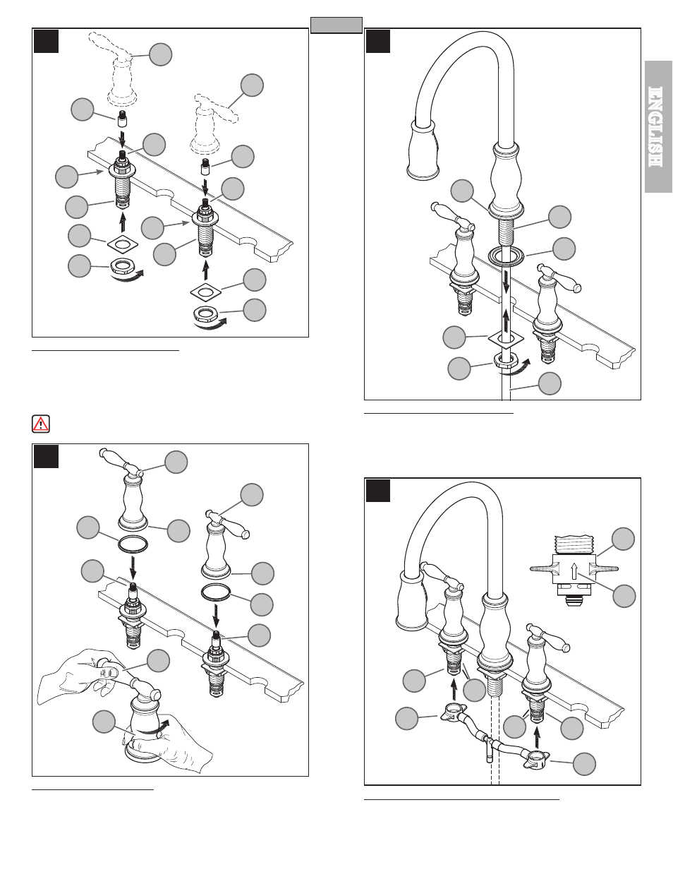
7 VALVE BODY INSTALLATION
Before proceeding, Valve Stems (
7A) are to be set in the closed position. From
underneath sink, place Square Washer (7B) onto Valve Shank (7C) and tighten loosely
with Mounting Nut (7D). Place Stem Extenders (7G) onto Valve Stems (7A). Temporarily
place Handle (7E) onto Valve Stem (7A) to make sure the handle levers are properly
aligned to sink. Remove Handle (7E) and tighten Mounting Nut (7D) until Valve Body
(7F) is firmly secured to sink.
Do not use Handles (
7E) to tighten or to rotate Valve Bodies (7F)!
8 HANDLE ATTACHMENT
Place Plastic Seal Rings (8A) against the bottom of Handle Hubs (8B). Connect Handles
(8C) onto Valve Adapters (8D) and be sure Valves and Levers are in the “OFF” position.
Secure handles by holding the Lever (8E) in place and tighten the Hubs (8B) by rotating
them in a clockwise direction.
To remove handles, rotate Hubs (8B) in a counterclockwise direction.
9 SPOUT BODY INSTALLATION
Apply plumber’s putty into groove on bottom of Gasket (9A) per manufacturer’s
recommendations. Place Gasket (9A) under base of Spout Body (9B). From above
sink, insert Mounting Shank (9C) through center hole of sink.
From underneath sink, place Square Washer (9D) and Locknut (9E) over Pull-Out Hose
(9F). Thread loosely onto Mounting Shank (9C). Tighten faucet firmly to sink.
10 HOSE CONNECTION TO VALVE BODY
Slide the End Connectors (10A) with arrow (10D) pointing up onto the Valve Bodies (10B).
Push the End Connectors (10A) all the way up until completely seated. Be careful not
to damage O-Rings (10C).
Reverse steps to remove Hose Connection.
3
10C
10C
7A
7B
7B
7D
7D
7A
7G
7G
7C
7F
7C
7F
7E
7E
9A
9C
9D
9E
9F
9B
10B
10A
10A
10A
10D
10B
8A
8B
8E
8B
8A
8B
8C
8C
8D
8D