Appendix, Waveforms and schematics – Watlow QPAC Modular SCR Power Control Service User Manual
Page 31
WATLOW QPAC Service Manual
31
Waveforms, Appendix
Appendix
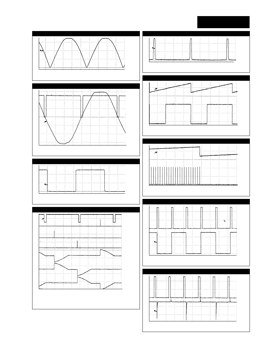
Figure 16
Scope Picture 1
2ms/div
FWZ QPAC-01 and QPAC-32 Base
Figure 17
Scope Picture 2
2ms/div
FWZ (top) Ref Sine Wave for QPAC-33 Base
Figure 18
Scope Picture 3
5us/div
MCK (TP 9) QPAC-33 Base , QAD Card (TP 4)
Figure 19
Scope Picture 4
2ms/div
1) (top) FWZ (TP6)
4) T-On C (U5-8)
6) Load On (T2)
2) T-On A (U8-12)
5) Load On (T1)
7) Load On (T3)
3) T-On B (U8-8)
Figure 20
Scope Picture 5
2ms/div
FWZ CA or CD Card (U1-3), QBF Card (TP1)
Figure 21
Scope Picture 6
15ms/div
1) (top) Ramp QBF (TP2) 2) Comparator Out QBF (TP3)
5V/Div
5V/Div
2V/Div
2V/div
5V/div
2V/div
2V/div
Figure 22
Scope Picture 7
QBF
200ms/div
1) Ramp (TP2)
2) Gating Output (TP4)
Figure 23
Scope Picture 8
QBV
5ms/div
1) FWZ (TP1 and TP2)
2) Ref. Sine Wave (TP 2)
2V/div
2V/div
Figure 24
Scope Picture 9
QBV
5ms/div
1) FWZ (TP1)
2) Count Clear Delay (TP3)
2V/div
- 12LS Controller (111 pages)
- 8LS Controller (140 pages)
- 8PID Controller (55 pages)
- Addendum to EZwarePlus (50 pages)
- ANASCAN (62 pages)
- ANASOFT (95 pages)
- ANAWIN 2 (154 pages)
- ANAWIN 3 (23 pages)
- Calibrating Watlow Series 988 Family Process Controls (19 pages)
- CAS (98 pages)
- CAS200 (124 pages)
- CLS (180 pages)
- CLS200 (251 pages)
- CLS200, MLS300 and CAS200 (92 pages)
- Control Console (12 pages)
- CPC400 (230 pages)
- DIN-A-MITE Style A (9 pages)
- DIN-A-MITE Style B (14 pages)
- DIN-A-MITE Style C (22 pages)
- DIN-A-MITE Style D (9 pages)
- DIN-Mount Adapter Instruction Sheet, Rev A (1 page)
- Dual DAC (4 pages)
- EM Gateway (28 pages)
- E-Safe Hybrid Relay Rev B (4 pages)
- E-SAFE II Hybrid Power Switch (4 pages)
- EZwarePlus Programming (264 pages)
- EZ-ZONE PM (111 pages)
- EZ-ZONE PM PID (125 pages)
- EZ-ZONE PM Express Limit (34 pages)
- EZ-ZONE PM Express (35 pages)
- EZ-ZONE PM Integrated Controller (181 pages)
- EZ-ZONE RM Limit Module Rev C (127 pages)
- EZ-ZONE RMA Modul (79 pages)
- EZ-ZONE RMC (236 pages)
- EZ-ZONE RME (124 pages)
- EZ-ZONE RMH (161 pages)
- EZ-ZONE RUI/Gateway (62 pages)
- EZ-ZONE RM-Scanner-Modul (140 pages)
- EZ-ZONE ST (97 pages)
- F4 External Event Board - Rev.B (2 pages)
- HG Series Mercury Displacement Relay (6 pages)
- LogicPro (296 pages)
- Mercury Relay or MDR Retrofit (13 pages)
- MICRODIN (24 pages)
- MICRODIN (106 pages)