Chapter 4, Test procedures, Q01 and q32 – Watlow QPAC Modular SCR Power Control Service User Manual
Page 15: Q33 zero cross adjustment, Q01 and q32 q33 zero cross adjustment, Chapter 4 test procedures, Procedures
WATLOW QPAC Service Manual
15
Test Procedures, Chapter 4
Procedures
Chapter 4
Test Procedures
Q01 and Q32
No power base adjustments are required on the Q01 and Q32 models. See the
bias and gain control card procedures.
Q33 Zero Cross Adjustment
Follow this step by step procedure to test the Q33 zero cross adjustment.
Equipment Needed:
•
Dual trace oscilloscope
Procedure:
1. Set Channel A on the scope to 5 volts per division.
2. Set Channel B to 2 volts per division.
3. Center both channels vertically.
4. Place the zero cross jumper in the phase angle position. See Page 11 for
the board layout.
5. Unplug the control card.
6. Connect the scope common to test point COM on the mother board (next to
the control card plug).
7. Connect the Channel A probe to Test Point 1 (TP1), located on the upper
right corner of the mother board. The card is unplugged.
8. Connect the Channel B probe to Test Point 6 (TP6) FWZ.
9. Turn power ON.
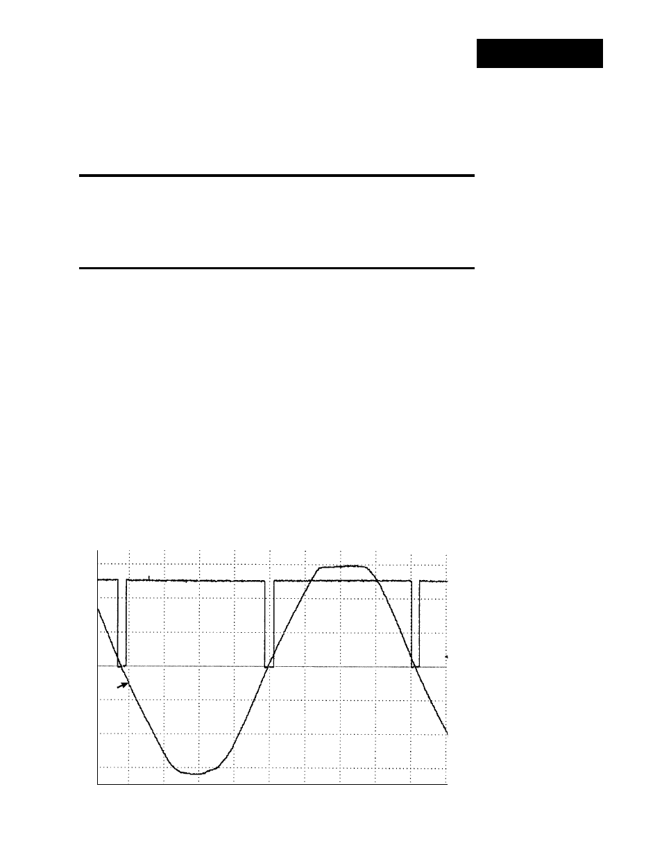
10. Adjust potentiometer P1 until the FWZ notch (Channel B) is centered on the
sine wave (Channel A). Refer to the scope picture below.
Figure 15 -
Q33 Scope Output
2ms/Div
5V/Div
2V/Div