3 attaching the power switch cover, 4 main memory installation, 5 expansion board (pci) installation – Proface APL3000B - Node Box PC User Manual
Page 76: 4 main
Chapter 3 Installation and Wiring
3-9
3.2.3
Attaching the Power Switch cover
For the AC type to conform to ANSI/ISA standards, the Power Switch cover needs to be attached to the main
unit.
The necessary torque is 0.5N
•
m to 0.6N
•
m.
3.2.4
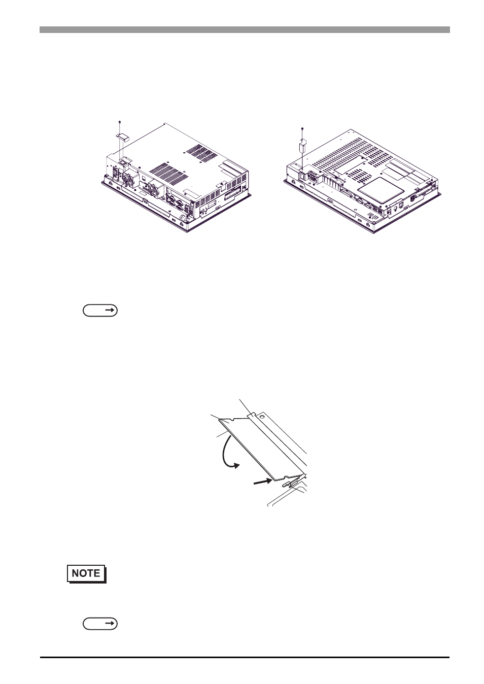
Main Memory Installation
(1)
Remove the PS-A unit's rear cover.
(2)
Angle the main memory module down slightly, and push it in until the connector pins mate with the
module's pins. Then, lower the module until it is horizontal and insert it completely into the connector.
This connector is shown in 3.2.2 PS-A Internal View.
(3)
Push in the main memory module until the stopper snaps into place.
3.2.5
Expansion Board (PCI) Installation
(1)
Remove the PS-A unit's rear cover.
SEE
"3.2.1 Removal/Attachment the Rear Cover" (page 3-6)
• The Expansion Board (PCI) is corresponding to PS-3710A units.
SEE
"3.2.1 Removal/Attachment the Rear Cover" (page 3-6)
PS-3710A Series
PS-3711A Series
Connector
Main Memory
Stopper
(2)
(3)