Internal switches of the control box – Proface APL3000B - Node Box PC User Manual
Page 7
7
• Make sure to turn off the power supply before using the switches. Adjusting the
switches while power is supplied may cause errors.
1.
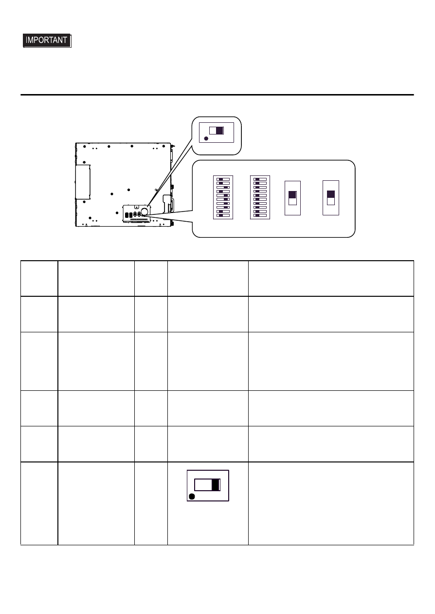
Internal switches of the control box
SW5
1 10
1 10
SW4
SW1
SW2
SW3
OFF
ON
ON
OFF
Bottom face of the control box
(CI)RI
5V
Switch
Location
Switch Name
Com-
patible
I/F
Factory
Settings
Description
SW1
System Set
Switch
–
See
10-point DIP switch. For System Set
Switch and the factory settings
details, see
SW2
Serial Mode
Select Switch
COM1
All OFF
(RS-232C)
10-point DIP switch. Designates
COM1 communication settings.
For Serial Mode Select Switch
details, see
SW3
CI(RI)/+5V
Changeover
Switch
COM2 CI(RI)
Not available on the built-in battery
unit version.
SW4
CI(RI)/+5V
Changeover
Switch
COM1 CI(RI)
Changes # 9 pin (CI(RI) / +5V).
SW5
*1
DVI Cable
Selection
Switch
–
Side without the
symbol
Q
(FP-DV01-100 is
not supported)
Toggles between supporting and not
supporting the FP-DV01-100 [DVI-D
cable (10m)], a Pro-face FP3000
Series option.
For details, see
*1 .PL-3000B series only.