Maple Systems OIT4165A User Manual
Page 8
2.2. Power Supply Selection
• The power supply used to power the OIT should have an output between +12
and +30 VDC, meeting Class 2 power requirements. The voltage should
measure between +12 and +30V at the OIT between Pins 1 and 2 of the power
connector. A 24 VDC, 1.2 amp linear power supply dedicated to the OIT is
recommended.
• The power cable for the OIT should be 18AWG 2-conductor stranded wire with
a shield wire and protective shield (foil or braid). The shield of the OIT power
cable must be connected to earth ground at both ends of the cable. Please refer to
the “Connect OIT to Power” section for more information.
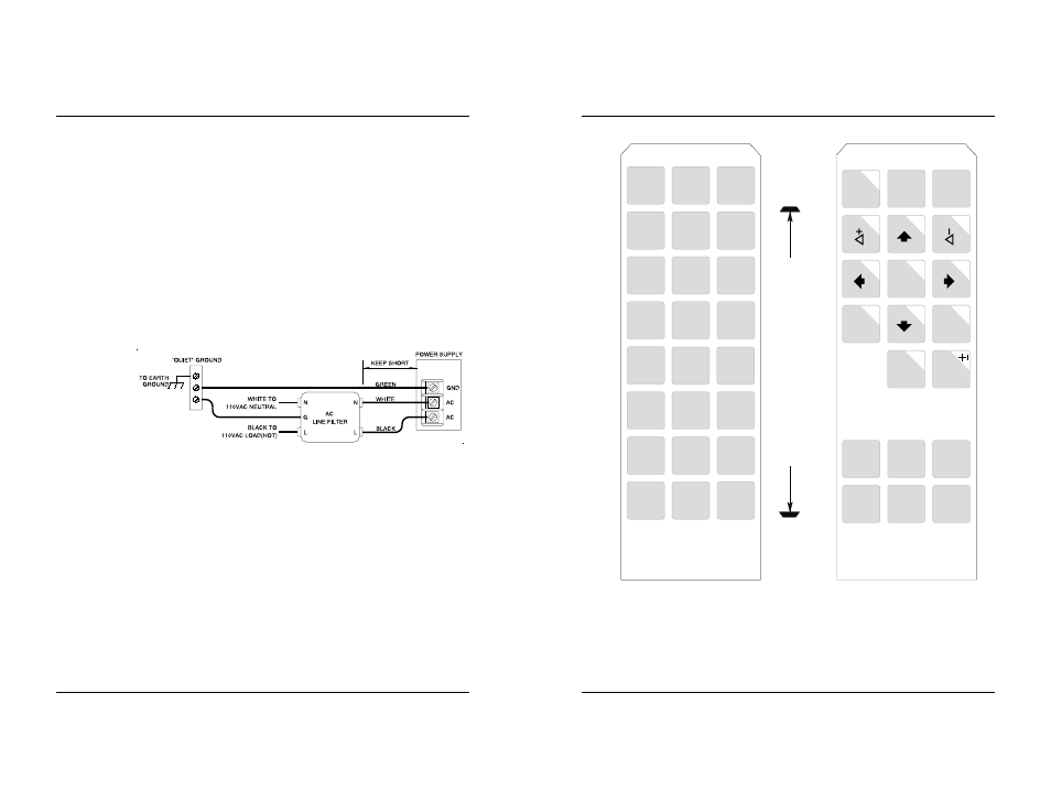
• A power line filter installed at the AC input to the OIT power supply is highly
recommended as a safeguard against conducted RF noise, which is often present
on factory power lines. The wires connecting the output of the power line filter
to the power supply should be kept as short as possible to minimize any
additional noise pickup. The case of the power line filter should be connected to
a quiet earth ground. The power line filter should have a current rating of at least
three amps with common mode and differential mode attenuation.
• The power supply that provides power to the OIT should not be used to power
switching relays or solenoids unless noise filter caps are connected to each relay.
2.3. OIT Cable Routing
• Input and output (I/O) wiring must be in accordance with Class I, Division 2
wiring methods and in accordance with the authority having jurisdiction.
• Always route the OIT communication cable and power cable away from any AC
voltage or PLC/host control wires.
• Never bundle the OIT cables together with 120 VAC power wires or with relay
wiring.
• Try to keep at least 8 inches (20 cm) of separation between the OIT cables and
other power wiring. If voltages greater than 120 VAC are used in the system,
greater separation is required.
• If the OIT cables must come near AC wiring, make sure they cross at 90 degrees.
• Running AC power wires in a separate grounded conduit is the preferred method
for electrical noise reduction.
1010-0102, REV 05
8
OIT3165A/4165A
Figure 2 Power Line Filter Connection
INSTALLATION MANUAL
17
1010-0102, REV 05
SD
F1
SD
F2
SD
F3
SD
F4
SD
F5
SD
F6
SD
F7
SD
F8
F1
F2
F3
F4
F5
F6
F7
F8
F9
F1
0
F1
1
F1
2
F1
3
F1
4
F1
5
F1
6
3160
Em
ul
at
io
n
EN
TE
R
CLEA
R
Al
ar
m
Ac
k
Ne
xt
Ms
g
He
lp
To
gg
le
La
st
Ms
g
Del
7
4
1
8
5
2
9
6
3
Pa
ge
Do
w
n
0
F1
F4
F2
F5
F3
F6
24
Func
ti
on
K
ey
s
C
he
ck
D
im
en
si
on
4.
00"
[101.
6
m
m
]
Figure 8 OIT3165/4165 Predefined Keypad Templates