SaltDogg PW22 User Manual
Page 2
Quality since 1946
Quality since 1946
5. Re-assemble the Pro-Wing and verify the pin
will rotate through the hole in the plow. If the pin
does not rotate through the hole, re-adjust the pin
bracket locations until it will. Mark the position of
the pin brackets.
6. The pin brackets may be attached by either
welding or bolting. (6a) If the brackets are being
welded into position, tack the brackets into
position and before welding complete, re-assemble
the Pro-Wing to verify the pin still rotates through
the 1-1/8” hole. (6b) When bolting the pin brackets
into position, mark the slot positions on the plow.
Wing on the rubber cutting edge from the rear.
Drill two 3/4” holes through the rubber cutting
edge where marked.
10. Remove the wing from the plow and bolt the
cutting edge to the wing using the 1/2” carriage
bolts, 5/8” flat washers and nuts supplied. Re-
assemble the Pro-Wing to the plow.
11. Repeat steps 2 through 10 for the passenger’s
side Pro-Wing.
12. Blade guides (not included) can be bolted on
when desired. See figure 6.
rotate the wing through the plow blade hole.
Assemble 5" x 5” washer over the pin and secure
the wing to the plow with three of the supplied
lynch pins. The 7/8” flat washers supplied are to be
used to remove any play between the Pro-Wing pin
and the 5" x 5” washer.
9. Verify the plow’s cutting edge on flat ground
and the a-frame either mounted to the truck or
level with the ground. Hold rubber cutting edge
tightly against the ground, the plow’s cutting edge
and the Pro-Wing as shown in figure 6. Mark the
location of the two holes in the bottom of the Pro-
.83
.79
1.13
5.5
14.1
4.50
4.88
Ø1.125
.562
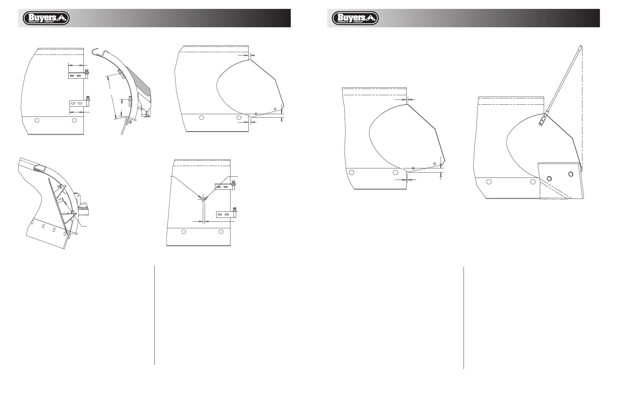
FIGURE 2.
APPROXIMATE LOCATION OF WING AFTER
THE PIN BRACKETS HAVE BEEN ADJUSTED
FIGURE 1.
CLAMP PIN BRACKETS AS SHOWN.
APPROXIMATE POSTION,
ADJUSTMENT REQUIRED.
MARK MADE IN
FIGURE 3.
FIGURE 4.
DRILL 1-1/8" HOLE TANGENT
TO THE MARKS MADE IN FIGURE 3.
FIGURE 3.
WITH THE PRO-WING'S PIN
AGAINST THE PLOW'S MOULD
BOARD, MARK MOULD BOARD AT
OUTSIDE & CENTER OF PIN.
.22
1.10
.34
FIGURE 5.
APPROXIMATE LOCATION OF
WING AFTER INSTALLATION.
FIGURE 6.
LOCATION OF CUTTING EDGE.
BLADE GUIDE INSTALLATION.
Mark the centers for each of the four bolt holes
required. For Meyer™ plows, the outer bolt hole
must go through the point of the outside rib. For all
other plows, verify that the holes will avoid the ribs
on the backside of the plow. Drill four 3/8” holes in
the positions marked.
7. Assemble the pin brackets to the plow using the
3/8” x 1” bolts, lock washers, and nuts supplied.
For Meyer™ plows, use 2-3/4” long bolts in place of
the 1” long bolts to go through the outer rib.
8. Place the Pro-Wing on the pin brackets and