Main components, 5 cut here – SaltDogg 1450969SSH Municipal-Sized Hydraulic Hopper Spreader User Manual
Page 3
3
TM
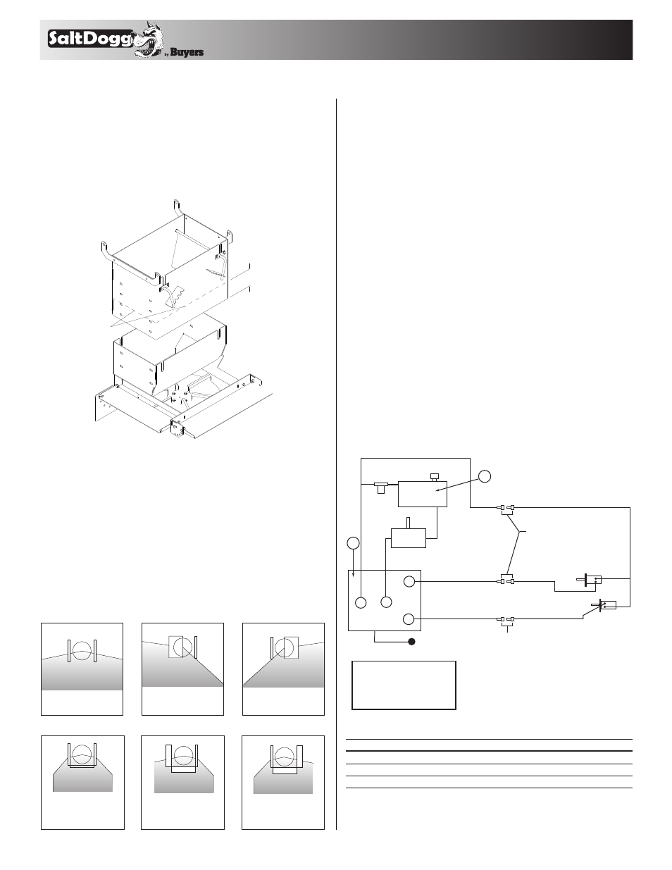
lower chute assembly up or down inside of upper
chute assembly. Adjustment slots are spaced by
3". Secure lower chute assembly using all 4 car-
riage bolts provided. Make sure all four bolts are
used for installation. To increase ground clearance
cut upper chute as shown and use lower slots in
bottom chute.
Installation Instructions – Hydraulic System
1. During assembly take precautions to keep all
hydraulic components as clean as possible.
2. Allow enough hose length to prevent kinking
and stretching of the hoses and to permit raising
the dump body. Support long hoses with wire ties
or clamps.
3. Protect hoses from wear caused by sliding and/
or vibration.
4. For proper rotation of conveyor chain and
spinner motors, hoses may be reversed.
5. Note: Use of a pipe joint sealant compatible with
hydraulic oil is recommended for all screw fittings.
6. Use swivel type hose ends to connect hoses to
flow valve. Damage to valve body may occur if the
fittings in flow valve are over tightened.
7. A 10 micron return line filter is recommended
to protect the pump, valve, and motors from wear
causing contamination.
8. Spreader Operation
Initial Priming and Inspecting of the System
Both internal
baffles out
Left baffle in,
Right baffle out
Right baffle in,
Left baffle out
All baffles adjusted
down for a confined
spread pattern
Right baffle deflects
material down;
heavy on right side
Left baffle deflects
material down;
heavy on left side
Internal Baffle Adjustment
External Baffle Adjustment
ON/OFF Lever
1/2" Quick Disconnects
3/4" (1)
Wire Hose
3/4" (1) Wire Hose
1/2" (1) Wire Hose
1/2" (1) Wire Hose
1/2" (1) Wire Hose
Conveyer
Chain Motor
Spinner Motor
3/4" Quick
Disconnects
3/4" (2) Wire Hose
1-1/4" Spiral
Suction Hose
10 Mircon
Filter
3/4" (2) Wire Hose
1/2" (1) Wire Hose
Tank
Pump
Valve
2
T
A
P
S
Valve Key
T= Tank/Reservoir
P= Pump/Pressure In
A= Auger (Conveyer Chain)
S= Spinner
(1) Single braid wire hose
(2) Double braid wire hose
1
1
HV715
1
Dual Flow Regulator Valve
2
SMR15S
1
15-Gallon reservoir
N/S
HVC1
1
Dual Flow Regulator Console
Item
part no.
qty.
descrIptIon
Main Components
"
5
Cut
Here
Spreader Operation
The spread pattern and the amount of material dis-
pensed will depend on the following factors:
• Conveyor speed.
• Spinner RPM.
• Feed gate door position.
• Baffle settings.
Below are illustrations that show the baffles effect
on the spread pattern as viewed from the top of the
spinner disk.