Performance charts, Hydraulic system requirements – Ramsey Winch 50K WILDCAT WINCH User Manual
Page 4
3 OM-914225-0209-B
HYDRAULIC SYSTEM REQUIREMENTS
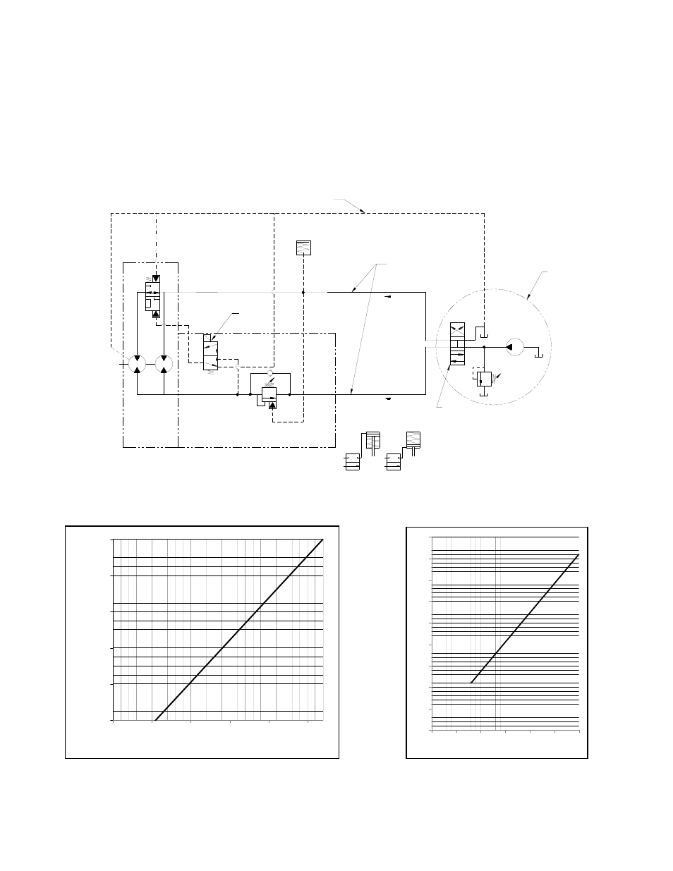
Refer to the performance charts, below, to properly match your hydraulic system to winch performance.
The charts consist of:
(1) Line pull (lb.) first layer vs. working pressure (PSI) and (2) line speed, first layer (FPM) vs. gallons per
minute (GPM). Performance based on a motor displacement of 10.3 cubic inches/rev with 60 GPM
maximum flow rate. Motor has (2) 1”-12 SAE straight thread o-ring ports.
Note:
A motor spool (open center) directional control valve is required for brake operation.
PERFORMANCE CHARTS
BASED ON 10.3 CU IN/REV MOTOR
PORT#3
COUNTER BALANCE/SPEED SELECTOR BLOCK
BRAKE
DIRECT LINE TO TANK
PAYOUT
COUNTER BALANCE
VALVE
RELIEF
4 WAY VALVE
3 POSITION
SYSTEM
PUMP
CUSTOMER
SUPPLIED
MOTOR CASE DRAIN
SAE -16
PORT #1
PORT #5
PAYIN
MOTOR 2 SPEED
1" TUBING SIZE
1" TUBING SIZE
SAE -16
LOW PRESSURE LINE
HIGH PRESSURE LINE
12 VDC
SHIFT SOLENOID
BAND BRAKE
CLUTCH
50K AIR CONNECTIONS
0
10000
20000
30000
40000
50000
0
500
1000
1500
2000
2500
PRESSURE (PSI)
FR
IS
T
LA
Y
ER
LI
NE
PU
LL
(L
B
S)
0
5
10
15
20
25
30
35
40
45
0
10
20
30
40
50
60
FLOW (GPM)
FI
R
ST
LA
Y
ER
LI
N
E
SP
EED
(F
P
M
)