Installation – Ramsey Winch REP-6000/8000/9000 User Manual
Page 4
4
Installation
The winches shown in this owner's manual are
solely and exclusively designed for vehicle mount-
ed, non-industrial applications. All other applica-
tions will void warranty.
Note: For specific bull-bar applications, the shifter
lever on the winch may need to be repositioned.
Refer to pages 6-7 for instructions in how to do
this.
It is very important that the winch be mounted on
a flat surface so that the three major sections (the
motor end, the cable drum and the gear housing
end) are properly aligned. It is recommended that
Ramsey kits be used to mount the winch. They
are designed to align the winch and distribute up
to the full rated load evenly, to avoid possible
damage to the winch or vehicle. Note: If recom-
mended mounting is not used, a kit of equal
design must be used.
Also available for mounting the REP winches are
winch mounting channels, short length (23.63")
#408052 (black), medium length (30.00")
#408120 (black) and long length (36.00")
#408101 (black). It is recommended that a
Ramsey mounting channel be used in all non-
Ramsey mountings.
Note: See the following separate sections for
attaching the wiring to the motor and solenoid for
the REP 6000/8000, REP 9000 12V, and REP
9000 24V models. The combined installation
instructions resume on the following page.
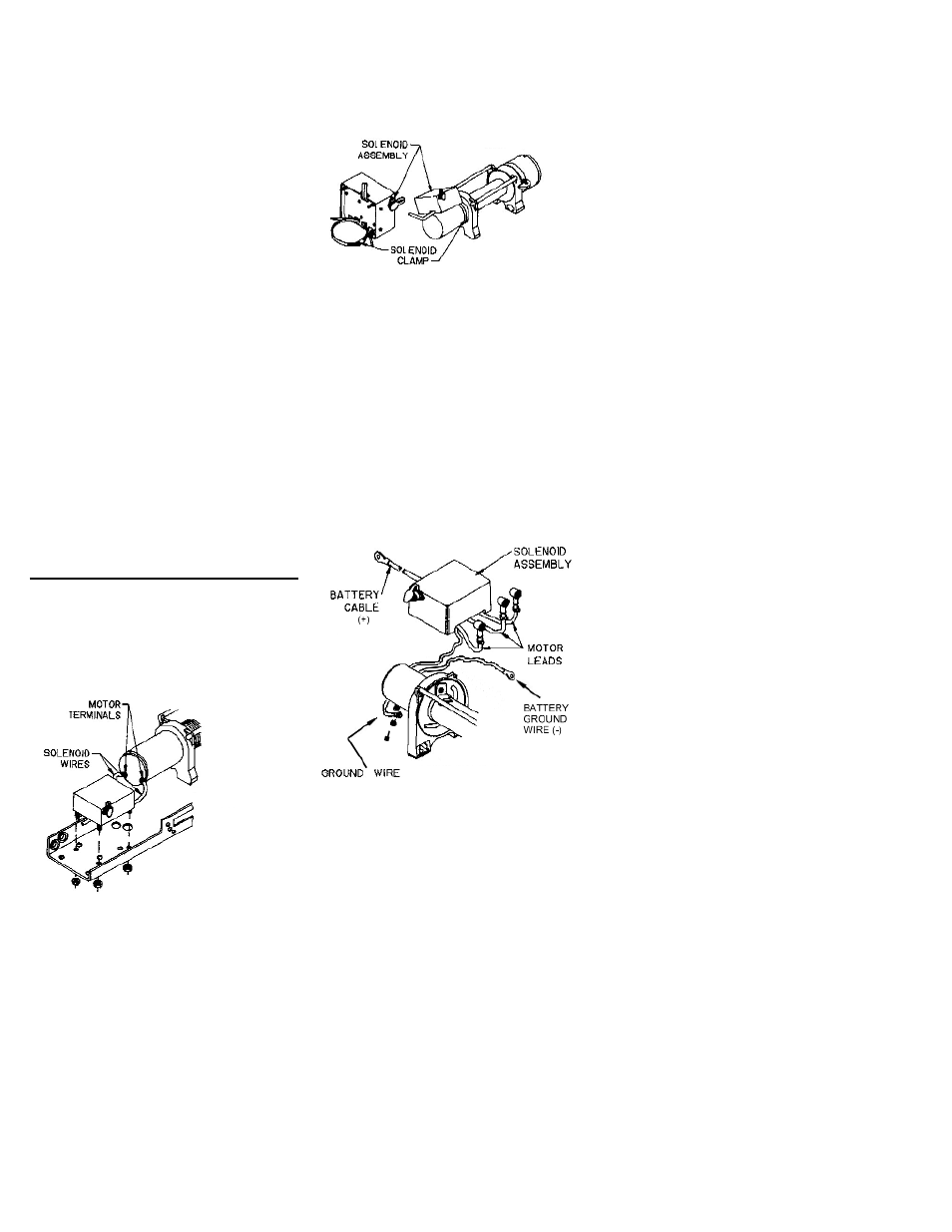
REP 6000/8000
When mounting winch, attach solenoid wires to
motor terminals at end of motor. TIGHTEN NUTS
ON MOTOR TERMINALS SECURELY (see FIGURE
1). Attach solenoid to mounting holes at end of
long channel (see FIGURE 1) or use solenoid
clamp to attach solenoid assembly to winch
motor (see FIGURE 2). Position solenoid at about
a 45° angle for clearance of lower winch guard
tube of kit. TIGHTEN CLAMP SECURELY.
REP 9000 12V
When mounting winch, connect labeled motor
leads coming from solenoid assembly to appro-
priately marked motor terminals. TIGHTEN NUTS
ON MOTOR TERMINALS SECURELY (see FIGURE
3). Attach solenoid ground wire to grounding bolt
located at bottom of motor (Battery ground wire is
already installed to grounding bolt on motor.)
Use solenoid clamp, as shown in FIGURE 2, to
secure solenoid assembly to winch motor. If
installing in combo mounting kit, position at about
a 45° angle for clearance of lower winch guard
tube in kit. Be sure that clamp is clear of motor
terminals at bottom of motor. TIGHTEN CLAMP
SECURELY.
FIGURE 1
FIGURE 2
FIGURE 3