Specifications, Wiring diagrams (cont), Com n/o – Aiphone DOOR RELEASE RELAY MODULE RY-24L User Manual
Page 3: Com n/c
Aiphone Communication Systems
1700 130th Ave. N.E.
Bellevue, WA 98005
(425) 455-0510
FAX (425) 455-0071
Toll Free Technical Support:
1-800-692-0200
E-mail [email protected]
Page 3
RY-24L Instr.
0210JD
SPECIFICATIONS:
Power Source:
Supplied by master station or CEU
Mounting:
No mounting required
Terminations:
Color-coded prewired pigtails
Relay Input:
24V DC, Red and Black wires, 22AWG
Relay Output:
Brown, Red, Orange wires, 18AWG
N/O Output rating:
5A at 30V DC or 125V AC
N/C Ouptut rating:
3A at 30V DC or 125V AC
Wiring:
2
conductors from unit’s door release contacts to RY-24L.
2 conductors from RY-24L to release mechanism, with power wired in series.
Dimensions (HxWxD): 1-3/4" x 7/8" x 7/16", with wires extending approx. 7-1/2"
D1 D3 D5 D7
D2 D4 D6 D8
DOOR RELEASE RELAY
L1 L2 L3 L4 L5 L6 L7 L8
M1 M3
M2 M4
VCH1 VCH2
X1 OUT X2
AX-320C
CO
+ - + -
D-PS V-PS
RS-232C
POWER
VIDEO OUT
V1 V2
AIPHONE AX-084C
AX-8MV
Master #1
AX-DV
Door #1
PS-
2420UL
+
-
PS-
2420UL
+
-
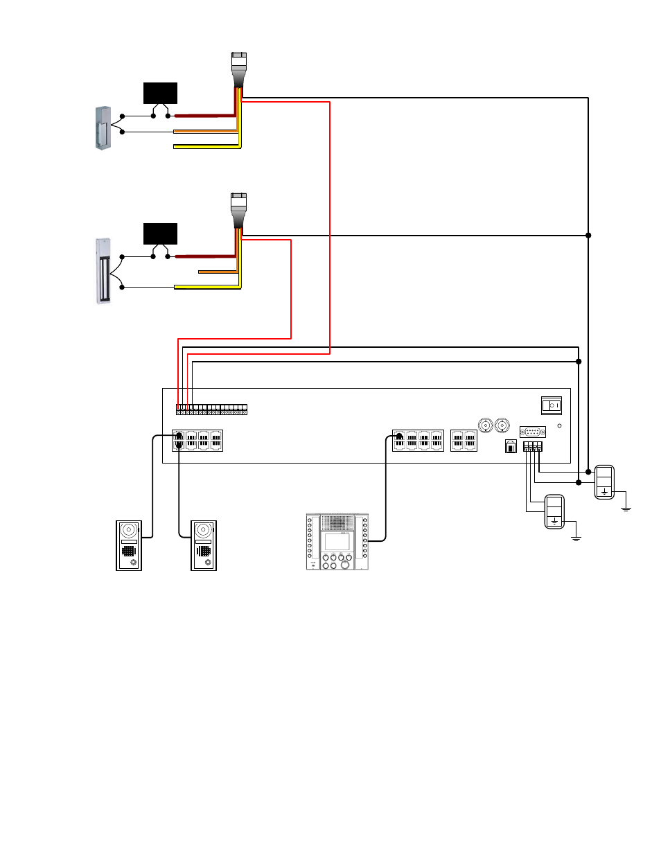
Connect separate RY-24L relay for each door release contact being used.
WIRING DIAGRAMS (cont):
AX-DV
Door #2
AX System Wiring
R
e
d
Blk
Brn
Org
Yel
COM
N/O
Use Brown & Orange wires when
connecting to Electric Strike.
LOCK
POWER
R
e
d
Blk
Brn
Org
Yel
COM
N/C
Use Brown & Yellow wires when
connecting to Maglock.
LOCK
POWER
NOTE: The door release contacts are rated at 24V AC/DC,
500mA. The RY-24L should be used in any application where
the strike or maglock has a higher voltage or draws more
current. Otherwise, internal damage to the AX Exchange Unit
could result.