1 atto fibrebridge 2370e physical attributes, Board dimensions, Cooling and airflow – ATTO Technology 2400C/R/D User Manual
Page 8: Power, Fibre channel port, Scsi ports, Management access, Led indicators
3
ATTO Technology Inc. FibreBridge Installation and Operation Manual
1.1 ATTO FibreBridge 2370E Physical Attributes
The ATTO FibreBridge 2370E is a 4-Gigabit Fibre Channel to SCSI bridge offering the ability to add 4-Gigabit
Fibre Channel connectivity to Ultra320 SCSI devices.
The FibreBridge 2370E is available in an embeddable
card for easy integration into storage devices.
Board dimensions
Width: 3.9 inches
Length: 7.995 inches
Height of tallest component: .55 inches on top, 0.1
inches on bottom
Cooling and airflow
Operating temperature: 0-40 °C
Humidity: 10-90% non-condensing
Power
4-pin power connector
4
2
1
3
+12V GND GND +5V
The FibreBridge board is
powered from a standard 4-
pin disk drive power
connector.
Input voltage and power draw: 5.0V = 10 Watts,
12V = 24 Watts
Fibre Channel port
The 4-Gb Fibre Channel port uses a Small Form factor
Pluggable (SFP) interface.
SCSI ports
The two independent SCSI ports are Ultra320 SCSI
busses with internal HD68 connectors, downward
compatible with all forms of single-ended SCSI and all
previous SCSI protocols.
Management access
The 10/100 Base T Ethernet port is accessible from
the RJ-45 connector to provide local and remote
diagnostics, monitoring and management.
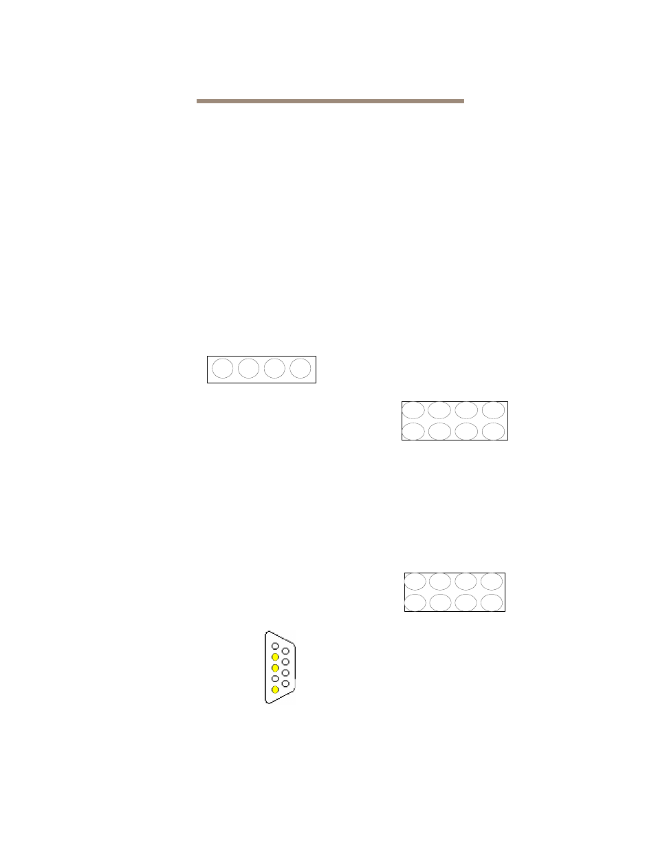
A serial 10-pin header provides
support for an RS-232 remote
monitoring and management port
through the Command Line
Interface. The baud rate is
programmable and preset at the
factory to 115200 bps.
LED indicators
On-board LED indicators are on the board front or LED
headers may be connected to outside panels.
SCSI ports: a green LED indicates activity if it is lit,
no activity if it is off.
Fibre Channel port: a green LED indicates activity if
it is lit, no activity if it is off. A separate green LED
indicates speed: you may set the LED to signify 1
Gb/sec or 2 Gb/sec if it is off or 4 Gb/sec or 2 Gb/sec
if it is on.
A Ready LED lights green to indicate ready and is off
to indicate not ready.
A Power Status LED is on to indicate 5V and 12V
are applied to the board; flashing green indicates that
12V is applied but 5V is not.
A Yellow LED indicates fault status: off means not
faulted; on means faulted status.
Embedded in the Ethernet port connector: a
lighted green LED shows a valid link; off indicates that
no link is present. A separate blinking yellow LED
indicates activity.
LED Header P5 Pins
LED Header P6 Pins
1
9
8
7
6
5
4
3
2
RX
TX
GND
1 Ready LED Cathode
2 VDD 3.3
3 Power OK LED Cathode
4 VDD 3.3
5 Fault LED Cathode
6 VDD 3.3
7 NC
8 NC
1 SCSI Port 1 Activity LED Cathode
2 VDD 3.3
3 SCSI Port 2 Activity LED Cathode
4 VDD 3.3
5 Fibre Channel Port Speed LED Cathode
6 VDD 3.3
7 Fibre Channel Port Activity LED Cathode
8 VDD 3.3
7
2
1
4
3
6
5
8
2
7
8
5
6
3
4
1