1 pm-p006ups system block diagram – IEI Integration PM-P006UPS User Manual
Page 14
PM-P006UPS DC/DC Converter Module
Page 6
2.1 PM-P006UPS System Block Diagram
154H154H162H
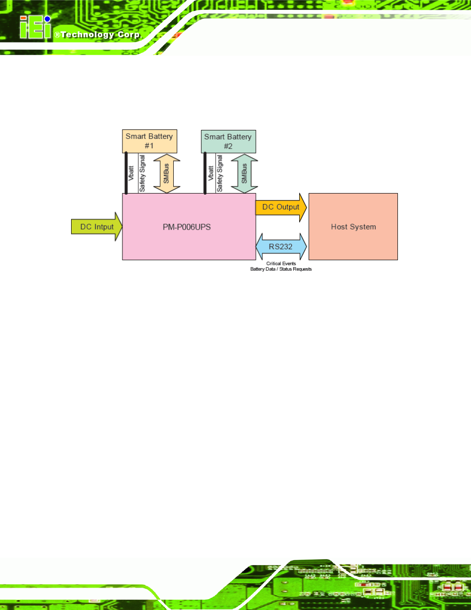
Figure 2-1
shows the system block diagram of the PM-P006UPS. The detailed
descriptions of the system operation are described in the following sections.
Figure 2-1: PM-P006UPS System Block Diagram
The PM-P006UPS is a charging circuit that provides the Smart Battery with charging
current and charging voltage from DC input to match the requirements from Smart Battery.
The PM-P006UPS also provides DC output power to the Host System with following
features:
Provide stable and uninterruptible power to equipment during a power outage,
line sags and spikes
Absorb power surges and transients
Smooth out noisy power sources
The PM-P006UPS receives critical events from the Smart Battery when it detects a
problem. The Smart Battery communicates with PM-P006UPS via two separate
communication interfaces:
The SMBus CLOCK and DATA lines (primary communication channel)
The secondary signaling mechanism or Safety Signal (secondary