8 jumper settings, 9 compactflash® card installation, Umper – IEI Integration PPC-37xx-N270 v1.01 User Manual
Page 51: Ettings, Ompact, Lash, Nstallation, Figure 4-3: ppc-3712 back cover retention screws
PPC-37xx-N270 Panel PC
Page 35
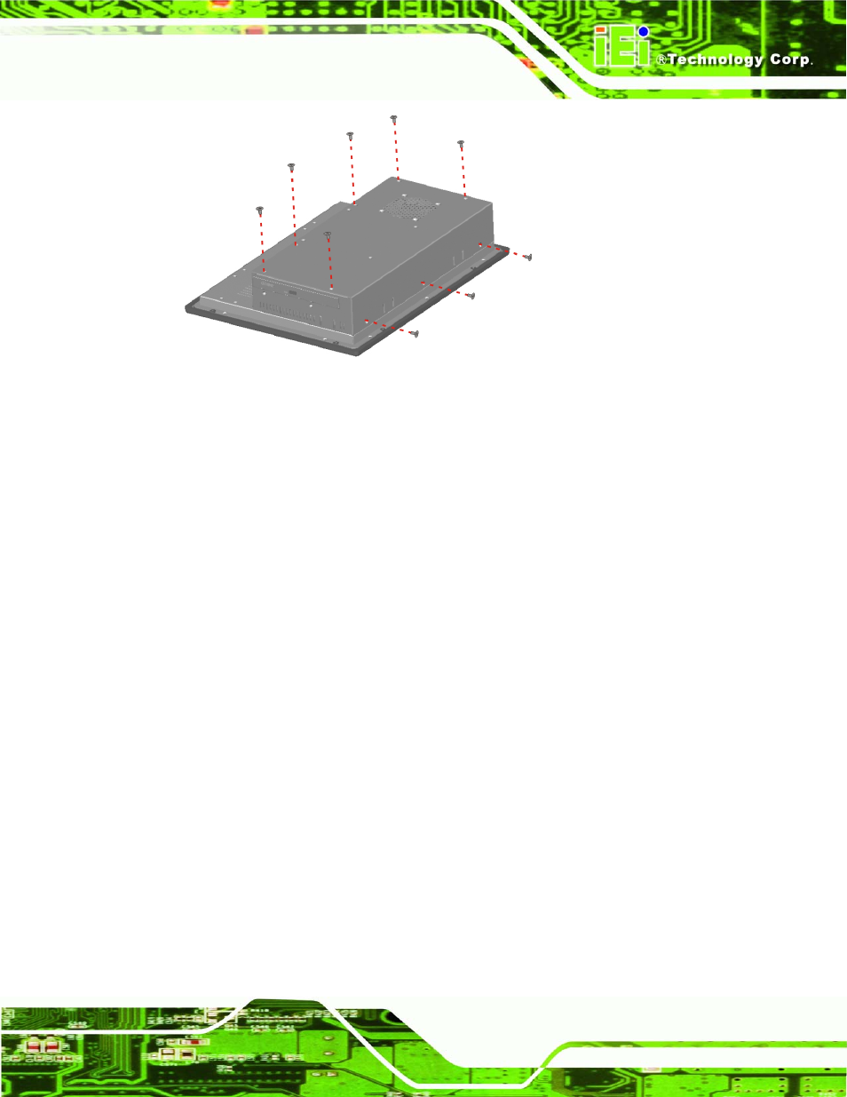
Figure 4-3: PPC-3712 Back Cover Retention Screws
4.8 Jumper Settings
The jumper settings are all described in Section 4.8. During normal installation, these
settings should not be changed
4.9 CompactFlash® Card Installation
To install the a CF Type II card onto the PPC-37xx-N270, please follow the steps below:
Step 1:
Locate the CF card socket
. Place the PPC-37xx-N270 on an anti-static pad
with the solder side facing up. Locate the CF card socket.
Step 2:
Remove
the CF card socket cover. The socket cover is secured to the chassis
with two retention screws. Remove the two retention screws to remove the
socket cover.
Step 3:
Align the CF card
. Make sure the CF card is properly aligned with the CF
socket.
Step 4:
Insert the CF card
. Gently insert the CF card into the socket making sure the
socket pins are properly inserted into the socket. See Figure 4-4.
Step 0: