2 internal peripheral connectors, Nternal, Eripheral – IEI Integration TANK-820-H61 v1.00 User Manual
Page 56: Onnectors, Figure 4-2: system motherboard (rear)
TANK-820 Em b e d d e d S ys te m
P a g e 43
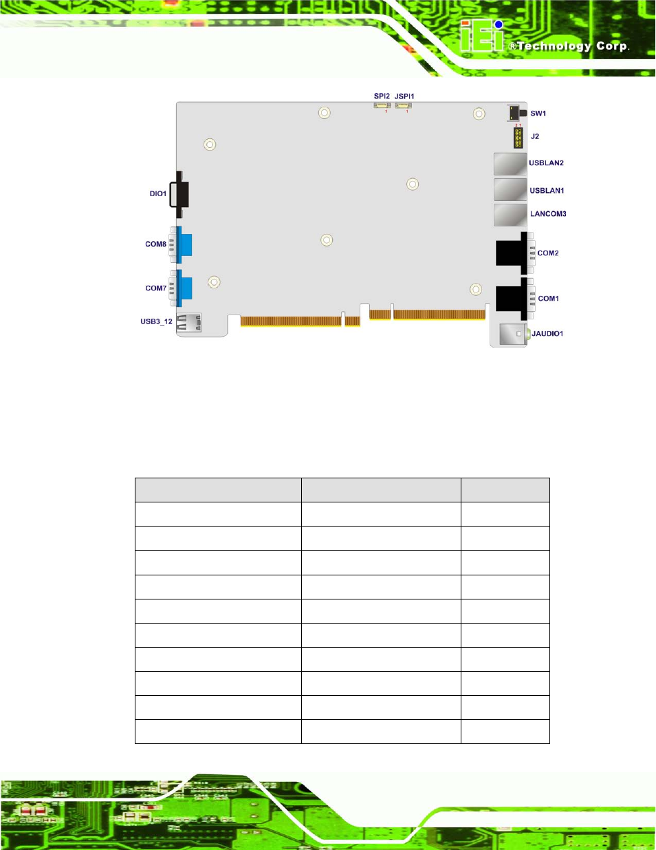
Figure 4-2: System Motherboard (Rear)
4.2 In te rn a l P e rip h e ra l Co n n e c to rs
The table below shows a list of the internal peripheral interface connectors on the system
motherboard. Pinouts of these connectors can be found in the following sections.
Co n n e c to r
Typ e
La b e l
Battery connector
2-pin wafer
BAT1
BIOS programming connector
6-pin wafer
SPI2
CompactFlash® Type II socket
CompactFlash® Type II socket
CF1
CPU fan connector
4-pin wafer
CPU_FAN1
DDR3 SO-DIMM slot
DDR3 SO-DIMM slot
DIMM1
EC debug connector
18-pin header
CN4
EC programming connector
6-pin wafer
JSPI1
LED connector
12-pin header
J2
PCH fan connector
3-pin wafer
PCH_FAN
SATA 3Gb/s drive connectors
14-pin SATA connector
SATA1
- KM-088G (5 pages)
- ECW-281B_D2550 (159 pages)
- ECW-281B_B2-N270 v3.01 (189 pages)
- ECW-281B_B2-N270 v2.00 (180 pages)
- ECW-281B_B2-N270 v2.10 (179 pages)
- ECW-281B_B2-D525 (137 pages)
- IBX-530B-N270 (133 pages)
- uIBX-200-VX800 v1.04 (113 pages)
- uIBX-200-VX800 v2.00 (116 pages)
- uIBX-200-VX800 v2.10 (116 pages)
- uIBX-200 v1.02 (109 pages)
- uIBX-200 v1.10 (113 pages)
- uIBX-210-CV-N2600 (163 pages)
- TANK-101B-D525_N455 v1.02 (119 pages)
- TANK-101B-D525_N455 v1.00 (118 pages)
- TANK-101B-D525_N455 v1.10 (119 pages)
- TANK-800-D525 v1.00 (116 pages)
- TANK-800-D525 v1.14 (137 pages)
- TANK-600-D2550_N2600 (132 pages)
- TANK-GM45A (104 pages)
- TANK-700-QM67 v1.00 (128 pages)
- TANK-700-QM67 v1.12 (145 pages)
- TANK-700-QM67 v2.00 (144 pages)
- TANK-720-Q67 (147 pages)
- TANK-820-H61 v2.00 (158 pages)
- TANK-820-H61 v2.03 (157 pages)
- TANK-6000-C226 (138 pages)
- IDS-H61 (72 pages)
- IOPS-Q67_H61 (70 pages)
- ECN-680A-H61 (190 pages)
- ECN-780-Q67 (184 pages)
- ECN-360A-HM65 (154 pages)
- ECN-360A-D2550 (141 pages)
- EBC-2102 (5 pages)
- ECN-581A-R10-HM551 (6 pages)
- EBC-3200 (6 pages)
- EBC-3100 (8 pages)
- EBC-3000 (7 pages)
- EBC-2100 (4 pages)
- EBC-3620 (8 pages)
- VSTAND (1 page)
- AUPS-C20 v1.01 (49 pages)
- AUPS-C20 v1.02 (55 pages)
- AUPS UART Protocal SPC (11 pages)