2 peripheral interface connectors – IEI Integration IMBA-G412ISA v2.00 User Manual
Page 31
2012/1/202012/1/20
IMBA-G412IS A ATX Mo th e rb o a rd
P a g e 17
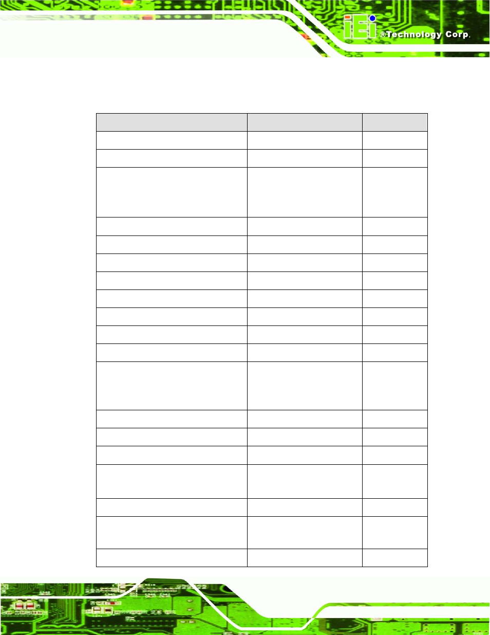
3.1.2 P e rip h e ra l In te rfa c e Co n n e c to rs
The table below lists all the connectors on the board.
Co n n e c to r
Typ e
La b e l
Audio connector
10-pin header
FP_AUDIO1
Fan connector (CPU)
4-pin wafer
CPU_FAN1
Fan connector (system)
3-pin wafer
NB_FAN1,
SYS_FAN1,
SYS_FAN2
CompactFlash® slot
CF Type II slot
CF1
CPU power input connector
4-pin connector
CPU12V1
Digital I/O connector
10-pin header
DIO1
Front panel connector
14-pin header
F_PANEL1
IDE connector
40-pin box header
IDE1
Infrared connector
5-pin header
IR1
ISA slots
ISA slot
ISA1, ISA2
Memory slot
240-pin DDR3 DIMM slot
DIMM1, DIMM2
PCI slots
PCI slot
PCI1, PCI2,
PCI3, PCI4,
PCI5
PCIe x16 slot
PCIe x16 slot
PCIE1
PCIe power connector
4-pin connector
PCN1
Power connector
24-pin connector
PWR2
RS-232 serial port connector
10-pin box header
COM3, COM4,
COM5, COM6
RS-232/422/485 serial port connector
14-pin box header
COM2
SATA drive connectors
7-pin SATA drive connectors
SATA1, SATA2,
SATA3, SATA4
SMBus connector
4-pin wafer
SMBUS1