Installation – Vestil PM5-TG Foot Guard User Manual
Page 4
rev. 1/16/2013
PM5-TG, manual
Copyright 2013 Vestil Manufacturing Corp.
Page 4 of 5
Installation
Attach the foot guard to the steering shaft of your pallet truck:
Step 1: Turn the pallet truck yoke 90 degrees clockwise (to the right) so that the steering
wheels are perpendicular to the rest of the truck.
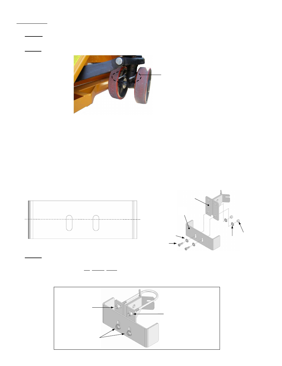
Step 2: Install the formed threaded rod around the steering shaft as shown below.
Step 3: {Refer to FIG. 3A & 3B] Fasten the formed toe guard (2) to the toe guard weldment (1)
to make the toe guard assembly. NOTE: a) The slotted openings in the formed toe guard are
offset vertically from the centerline, i.e. are closer to one side than the other. Because of this
offset, the minimum clearance between the ground and the bottom edge of the formed toe
guard varies depending on the orientation of the formed toe guard (edge A on top or edge B on
top). If the formed toe guard is installed with edge B on top, the clearance between the toe
guard and the ground will be smaller. Select the orientation that is appropriate for your pallet
truck to provide between ½ in. and ¾ in. clearance. b) The formed toeguard must be able to
slide up and down, so do not tighten the lock nuts (on the shoulder screws) so much that the
toeguard is prevented from sliding.
Step 4: Slide the assembly onto the ends of the threaded rod (6), and fasten the assembly to
the rod with washers and lock nuts. If necessary, adjust the position of the bottom edge of the
formed toe guard to be no more than ¾ in. above the ground. Also make sure that both sides
of the bottom edge are the same height above the ground, and then tighten the lock nuts.
Remove excess length from the ends of the threaded rod and/or cap with acorn nuts.
Threaded rod (6)
installed around
steering shaft
FIG. 3A: Offset slots
A
B
Center line
FIG. 3B: Fasten formed toe guard
(2) to toe guard weldment (1)
3
4
5
4
2
1
Loosen and adjust
position of toe guard
Fasten assembly
to threaded rod (6)
using
5
/
16
in. USS
flat washers and
lock nuts
FIG. 2: Install
threaded rod
Cut ¼ in. to ½ in.
beyond lock nut to
remove excess
length
-OR-
Cap with acorn nuts