TREND T_TS User Manual
T/ts, Space temperature sensor, Installation instructions
1
T/TS Space Temperature Sensor Installation Instructions TG101133A Issue 2/B 20/02/07
Important: Retain these instructions
Installation Instructions
T/TS
Space Temperature Sensor
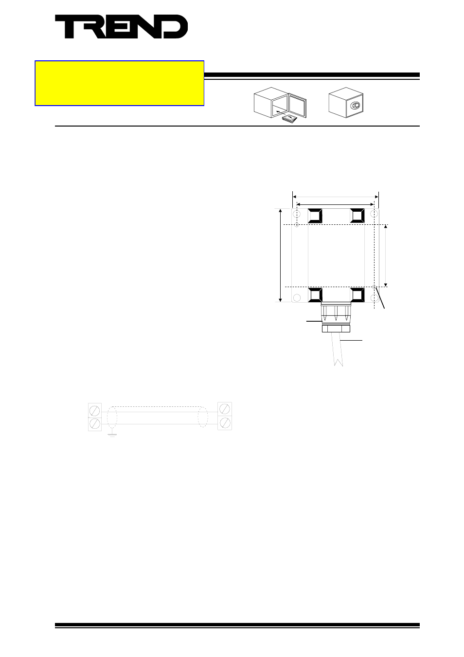
View of underside
No 6 (M3.5)
screw hole
cable to IQ
M20 cable gland
INSTALLATION
The sensor should be mounted on a wall, away from sources of heat and out of direct sunlight.
Thermistor
IQ Input Channel
Sensor
C
I/P
polarity
independent
(4)
Wire as shown below and replace cover.
(5)
Replace cover and tighten screws.
(6)
Set IQ input channel link for thermistor input.
(1)
Remove cover by unscrewing 4 retaining
screws.
(2)
Fix to wall using 2 no.6 (M3.5) screws, through
holes on centres as shown.
(3)
Route the cable through the cable entry.
Note: this sensor can be used to measure radiant heat. Ensure the sensor is mounted in a position where a good representation
of the radiant heat can be measured.
75 mm (2.95”)
63 mm (2.48”)
80 mm (3.15”)
52 mm (2.05”)
A4 double sided
- PN-VPC (2 pages)
- DPCM (24 Vac_dc) (4 pages)
- 2VID (24 Vac_dc) (4 pages)
- 6RM_24VAC (4 pages)
- 3RM_24VAC (4 pages)
- 2RM_24VAC (4 pages)
- 2SRM (24 Vac_dc) (4 pages)
- SRMAC (4 pages)
- 4DiX_24Vac (4 pages)
- AD20-xx (4 pages)
- AD05-xx (4 pages)
- AL0406-P-SU (2 pages)
- AL0206-P-K (2 pages)
- ACCA_VB_ADK (1 page)
- AT0102-24 (2 pages)
- V162X (4 pages)
- V584 (2 pages)
- V583 (2 pages)
- NXIP (8 pages)
- NXNI (8 pages)
- NX Variable Speed Drives (136 pages)
- NXL Variable Speed Drives (12 pages)
- XW_R_IQ (4 pages)
- ACCW_RW_IQ (4 pages)
- TW_S (4 pages)
- TW_P (4 pages)
- PCW_... (4 pages)
- OCC_U (4 pages)
- LLO (4 pages)
- LLS (4 pages)
- WS_R (2 pages)
- WS_S, _SD (4 pages)
- AQ_S (4 pages)
- AQ_D (4 pages)
- DPSL (4 pages)
- DPSA (4 pages)
- PIl3 (4 pages)
- DPIL (4 pages)
- DPIA (2 pages)
- HT_O (8 pages)
- HT_D (4 pages)
- HT_S (4 pages)
- T_FS (4 pages)
- T_FG (4 pages)
- T_AV (4 pages)