TREND T_PO User Manual
Page 2
T/PO
Installation Instructions
T/PO Installation Instructions TG100241A Issue 4/B 14/02/07
2
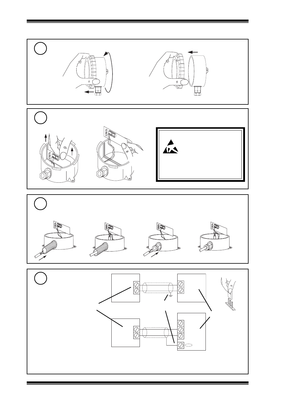
Remove Lid
Installation
(continued)
4
a
b
Wire to Controller
7
Insert Cable
6
either use M20 flexible conduit
or use M16 cable gland
Lift Board
5
IQ1xx, IQ2xx
polarity independent
Sensor
24 Vdc
IN
Terminate screen at IQ end only
Analogue input
channel linked
for current (I)
I
IQ system TP/I/22/HF/200
(Belden 8761) cable
recommended.
IQ3
Sensor
0 (0 V)
N (in)
Terminal size 0.5 to 2.5 mm
2
(14 to 20 AWG)
Note that if connecting to an IQ22x controller (including /ADL or /OC), do not connect directly to
C (+24V), instead connect to AUX+ (+24V).
+ (24 V)
Caution: This unit contains static
sensitive devices. Suitable
anti-static precautions
should be taken throughtout
the operation to prevent
damage to the units. BS EN100015/1
Basic Specification: protection of
electrostatic sensitive devices.
- PN-VPC (2 pages)
- DPCM (24 Vac_dc) (4 pages)
- 2VID (24 Vac_dc) (4 pages)
- 6RM_24VAC (4 pages)
- 3RM_24VAC (4 pages)
- 2RM_24VAC (4 pages)
- 2SRM (24 Vac_dc) (4 pages)
- SRMAC (4 pages)
- 4DiX_24Vac (4 pages)
- AD20-xx (4 pages)
- AD05-xx (4 pages)
- AL0406-P-SU (2 pages)
- AL0206-P-K (2 pages)
- ACCA_VB_ADK (1 page)
- AT0102-24 (2 pages)
- V162X (4 pages)
- V584 (2 pages)
- V583 (2 pages)
- NXIP (8 pages)
- NXNI (8 pages)
- NX Variable Speed Drives (136 pages)
- NXL Variable Speed Drives (12 pages)
- XW_R_IQ (4 pages)
- ACCW_RW_IQ (4 pages)
- TW_S (4 pages)
- TW_P (4 pages)
- PCW_... (4 pages)
- OCC_U (4 pages)
- LLO (4 pages)
- LLS (4 pages)
- WS_R (2 pages)
- WS_S, _SD (4 pages)
- AQ_S (4 pages)
- AQ_D (4 pages)
- DPSL (4 pages)
- DPSA (4 pages)
- PIl3 (4 pages)
- DPIL (4 pages)
- DPIA (2 pages)
- HT_O (8 pages)
- HT_D (4 pages)
- HT_S (4 pages)
- T_FS (4 pages)
- T_FG (4 pages)
- T_AV (4 pages)