Installation instructions ht/s 2 installation, Wire to controller, Assemble unit – TREND HT_S User Manual
Page 3: Configure iq
HT/S Space Humidity and Temperature Sensor Installation Instructions TG200990 Issue 1/A 30/01/08
3
Installation Instructions
HT/S
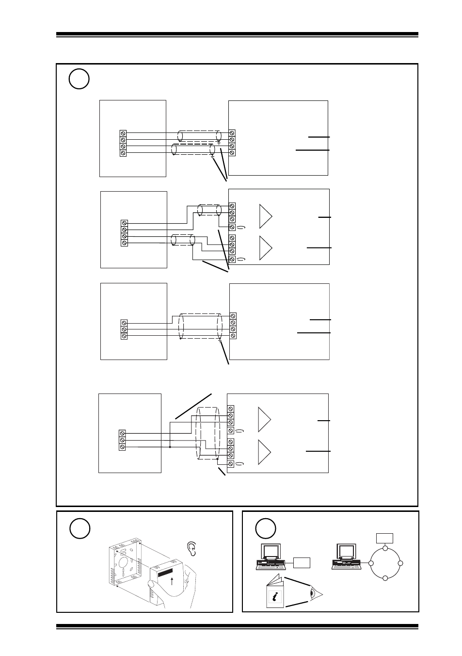
2 Installation
(continued)
Wire to Controller
7
Assemble unit
8
backplate
‘click’
Configure IQ
9
IQ Configuration
Manual 90-1533
IQ
IQ
or
0 (0V)
N+1 (in)
+ (+24V)
0 (0V)
N (in)
+ (+24V)
N+1
N
I-N
I-P
TH
TH
temperature
humidity
IQ3
linked for thermistor (T)
linked for current (I)
HT/S
earth (ground) screens at IQ end
I-N
I-P
TH
TH
IN
C
IN
C (+24V)
IQ1 & IQ2
}
temperature
}
humidity
linked for thermistor (T)
linked for current (I)
earth (ground) screens at IQ end
HT/S/2%
I1N
I-P
IN
IN
C (+24V)
I2N
C (+24V)
0 (0V)
N+1 (in)
+ (+24V)
0 (0V)
N (in)
+ (+24V)
N+1
N
I1N
I-P
I2N
IQ1 & IQ2
IQ3
earth (ground) screen at IQ end
earth (ground) screen at IQ end
Note that in order to maintain the HT/S/2% temperature sensor accuracy, the temperature sensor
should only be used if the humidity sensor is also used.
Note that when connecting to IQ3, in order to provide sufficient supply current to the sensor, the
sensor I-P terminal must be connected to both channels’ 24 V terminals.
}
temperature
}
humidity
linked for current (I)
linked for current (I)
temperature
humidity
linked for current (I)
linked for current (I)
2 analogue input channels